Content for TS 23.434 Word version: 19.2.0
0…
4…
5
6…
6.4…
6.5…
6.5.3…
7…
8…
8.2.2…
9…
9.3…
9.3.2.21…
9.3.3…
9.3.6…
9.3.11…
9.3.13…
9.3.14…
9.4…
9.4.6…
9.5…
10…
10.3…
10.3.2.22…
10.3.3…
10.3.7…
10.3.10…
10.4…
11…
11.3…
11.3.3…
11.4…
12…
12.3…
13…
14…
14.2.2.2…
14.3…
14.3.2.20…
14.3.2.40…
14.3.3…
14.3.3.3…
14.3.4…
14.3.4.6
14.3.4.7…
14.3.4A…
14.3.4A.3…
14.3.4A.4…
14.3.4A.6…
14.3.4A.8…
14.3.4A.9…
14.3.4A.10…
14.3.5…
14.3.6…
14.3.9…
14.3.12…
14.4…
15…
16…
17…
18…
A
B…
14.3.6 Event Monitoring
14.3.6.1 General
14.3.6.2 Monitoring Events Subscription Procedure
14.3.6.3 Monitoring Events Notification Procedure
14.3.7 5G TSC resource management procedures
14.3.7.1 General
14.3.7.2 TSC stream availability discovery procedure
14.3.7.3 TSC stream creation procedure
14.3.7.4 TSC stream deletion procedure
14.3.8 TSN resource management procedures
14.3.8.1 General
14.3.8.2 5GS TSN Bridge information reporting
14.3.8.3 5GS TSN Bridge configuration procedure
...
...
14.3.6 Event Monitoring |R17| p. 250
14.3.6.1 General p. 250
The VAL server utilizes the NRM server for monitoring the events related to its VAL UEs and receive the event reports. The NRM server shall subscribe to multiple core network services to fetch all the required events related to the multiple VAL UEs served by the VAL server and report the same to the VAL server with the event details.
To monitor and report the events related to the VAL UE from the 3GPP core network, the NRM server shall use the Monitoring Events procedures as specified in TS 23.502.
To monitor and report the analytics events related to the VAL UE, the NRM server shall use the procedures specified in TS 23.288.
14.3.6.2 Monitoring Events Subscription Procedure p. 250
14.3.6.2.1 General p. 250
The VAL server subscribes to the NRM server to monitor the events related to VAL UE(s). Based on the VAL server request, the NRM server consumes the relevant core network services to receive the events related to the VAL UE(s). The related procedure is illustrated in the next clause.
14.3.6.2.2 Procedure p. 251
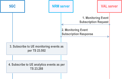
The procedure for VAL server subscribing to the NRM server, to monitor the VAL UE(s) related events is described in Figure 14.3.6.2.2-1.
Pre-conditions:
Step 1.
The VAL server sends Monitoring Events Subscription request to the NRM server, requesting the NRM server to monitor the events related to the VAL UE(s) as per the subscription request, and shall include the information related to the events that the VAL server is interested in.
Step 2.
The NRM server shall check if the VAL server is authorized to initiate the Monitoring Events Subscription request and if authorized, shall respond with Monitoring Events Subscription Response message, indicating the successful subscription status along with subscription information to the VAL server. The VAL service ID may be used by the NRM server to derive event specific information in 3GPP core network services (e.g. QoS requirement in analytics event subscription), based on e.g. local configuration. The NRM server maps the VAL group ID (if received) to the External Group ID known to the 3GPP core network.
Step 3.
Based on the events of interest information in the subscription request message, if applicable, the NRM server shall subscribe to the UE monitoring events (LOSS_OF_CONNECTIVITY, COMMUNICATION_FAILURE, etc.) for the set of UEs (VAL UEs) in the subscription request, as specified in TS 23.502.
Step 4.
Based on the events of interest information in the subscription request message, if applicable, the NRM server shall subscribe to the UE analytics events (like ABNORMAL_BEHAVIOUR etc.) for the set of UEs (VAL UEs) in the subscription request, as specified in TS 23.288.
14.3.6.3 Monitoring Events Notification Procedure p. 252
14.3.6.3.1 General p. 252
The NRM server receives the events related to VAL UE(s) from the 3GPP core network. The NRM server reports the monitoring events information to the VAL server.
14.3.6.3.2 Procedure p. 252
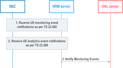
The procedure for NRM server notifying the VAL server with VAL UE(s) related events is described in Figure 14.3.6.3.2-1.
Pre-conditions:
- The VAL server has subscribed with NRM server using Monitoring Events Subscription Procedure as specified in clause 14.3.6.2;
Step 1.
If applicable, the NRM server receives the VAL UE related monitoring event notifications from the 3GPP core network as specified in TS 23.502.
Step 2.
If applicable, the NRM server receives the VAL UE related Analytics event notifications from the 3GPP core network as specified in TS 23.288.
Step 3.
The NRM server notifies the VAL server about the events related to the VAL UE in Notify Monitorng Events message. If multiple events are to be notified, then the NRM server may aggregate the notifications and send to the VAL server.
14.3.7 5G TSC resource management procedures |R17| p. 252
14.3.7.1 General p. 252
The procedures related to the 5G TSC network resource management are described in the following subclauses.
14.3.7.2 TSC stream availability discovery procedure p. 252
The TSC stream availability discovery procedure is used by the VAL server to discover the availability of resources for TSC communication for the given stream specification (i.e., between the target UEs) prior to creating the stream.
Pre-conditions:
- Each UE has an established Ethernet PDU session and DS-TTs are connected to the 5GS TSC bridge. The traffic classes are configured on each DS-TT.
- The NRM server has collected the 5GS TSC bridge management and port management information. The latter is related to the Ethernet ports located in the DS-TTs including bridge delay per DS-TT Ethernet port pair per traffic class.
- NRM server has calculated the bridge delay for each port pair, i.e. composed of (ingress DS-TT Ethernet port, egress DS-TT Ethernet port) including the UE-DS-TT residence time, packet delay budget (PDB) and propagation delay for both UL from sender UE and DL to receiver UE.
Step 1.
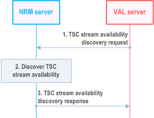
The NRM server receives a request from a VAL server on NRM-S reference point to discover the connectivity and available QoS characteristics between DS-TTs identified by the stream specification.
Step 2.
The NRM server validates the connectivity between the DS-TTs connected in the same 5GS TSC bridge based on the collected 5GS TSC bridge management and port management information, identifies the traffic classes supported by the DS-TTs and determines the end-to-end latency (including the UE-DS-TT residence times, PDBs and propagation delay).
Step 3.
NRM server responds to the VAL server with the stream specification and a list of traffic specifications with the available end-to-end latency and the traffic classes supported by the DS-TTs.
14.3.7.3 TSC stream creation procedure p. 253
This procedure allows the VAL server to create a TSC stream. The TSC stream creation procedure enables the VAL server to establish TSC connectivity with the required QoS between the UEs connected to the 5GS after the stream discovery procedure.
Pre-conditions:
- Each UE has an established Ethernet PDU session for its DS-TT port MAC address.
- Connectivity between the DS-TTs has been validated by the TSC stream availability discovery procedure specified in clause 14.3.7.2.
- The NRM server maintains mapping from the traffic class to TSC QoS.
Step 1.
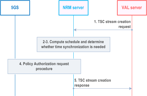
The NRM server receives a TSC stream creation request from a VAL server to create a TSC stream identified by a VAL Stream ID, between DS-TT ports in the stream specification and for the traffic class in the traffic specification.
Step 2.
The NRM server calculates the schedule for the VAL Stream ID based on the information collected earlier from the 5GS via N5. It provides per-stream filtering and policing parameters (e.g. as defined in IEEE 802.1Q [36]) used to derive the TSC QoS information and related flow information. NRM server also provides the forwarding rule (e.g. as defined in IEEE 802.1Q [36]) used to identify the DS-TT MAC address of the corresponding PDU session. Based on the 5GS bridge delay information it determines the TSC QoS information and TSC Assistance information for the stream.
Step 3.
Based on the Traffic specification (from the TSC stream creation request in step 1), the SEAL NRM server determines whether time synchronization needs to be activated for the TSC stream on the DS-TTs. If the DS-TTs are time synchronized, then the NRM does not activate the time synchronization for the corresponding DS-TT.
Step 4.
As a TSCTSF, the NRM server triggers via N84 the Npcf_PolicyAuthorization_Create service operation as described in TS 23.502 for the TSC stream for both UL QoS flow (sender UE to UPF/bridge) and DL QoS flow (UPF/bridge to receiver UE). The Policy Authorization request includes the DS-TT port MAC address, TSC QoS information, TSC Assistance Information (clause 5.27.2.3 of TS 23.501), flow bit rate, priority, Service Data Flow Filter containing flow description including Ethernet Packet Filters. The QoS flow will be assigned for the PDU session for the source MAC address for the UL direction and for the PDU session for the destination MAC address for the DL direction. This information is delivered to the DS-TT by the 5GS.
If time synchronization is determined to be needed for the TSC stream on the DS-TTs in step 3, the NRM server uses the procedures in clause K.2.2 of TS 23.501 to activate the time synchronization via the Npcf_PolicyAuthorization_Update service operation. The procedure includes the configuration and initialization of the PTP instance in the DS-TTs, the construction of PMICs to each DS-TT/UE to activate the time synchronization service in the DS-TT and to subscribe for the port management information changes in the DS-TTs.
Step 5.
The NRM server sends TSC stream creation response to the VAL server with the result of TSC stream creation for the VAL Stream ID.
14.3.7.4 TSC stream deletion procedure p. 254
This procedure allows the VAL server to delete a TSC stream.
Pre-conditions:
- The TSC stream is configured in the 5GS and the DS-TTs.
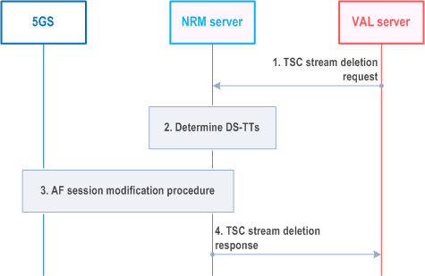
Step 1.
The NRM server receives a request from VAL server to delete a TSC stream for with a VAL Stream ID.
Step 2.
The NRM server identifies the MAC addresses of the DS-TTs involved in the stream based on the stored information for the VAL Stream ID. If none of the streams require to keep the time synchronization activated, the NRM server deactivates the time synchronization for the corresponding DS-TTs, otherwise keeps the time synchronization activated if the time synchronization for the DS-TTs was activated by the NRM server.
Step 3.
As a TSCTSF, the NRM server triggers via N84 the Npcf_PolicyAuthorization_Delete service operation defined in TS 23.502 for MAC addresses referred to by the VAL Stream ID. The NRM server uses the procedure to delete both UL QoS flow (sender UE to UPF/bridge) and DL QoS flows (UPF/bridge to receiver UE) from the PDU sessions of the UEs referred to by the VAL Stream ID. Before invoking the Npcf_PolicyAuthorization_Delete procedure, if the time synchronization service for the DS-TTs needs deactivation, the NRM server deactivates the time synchronization for the DS-TTs as described in clause K.2.2 of TS 23.501 via the Npcf_PolicyAuthorization_Update service operation.
Step 4.
The NRM server sends TSC stream deletion response to the VAL server with the result of TSC stream deletion for the VAL Stream ID.
14.3.8 TSN resource management procedures |R17| p. 255
14.3.8.1 General p. 255
The procedures related to the TSN network resource management are described in the following subclauses.
14.3.8.2 5GS TSN Bridge information reporting p. 255
Pre-conditions:
- There is already an established session between the TSN CNC and the NRM server acting as TSN-AF.
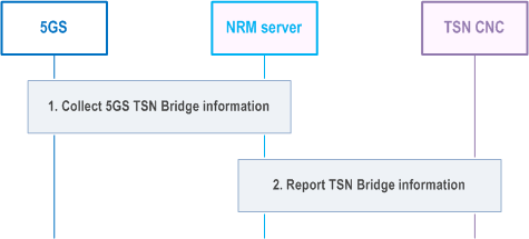
Step 1.
Acting as the TSN AF the NRM server collects 5GS TSN Bridge information by interaction with the 5GS via the N5 reference point, as described in in TS 23.502 Annex F.1. The NRM server stores the binding relationship between 5GS Bridge ID, MAC address of the DS-TT Ethernet port and also updates 5GS bridge delay as defined in clause 5.27.5 of TS 23.501. The NRM server retrieves txPropagationDelay and Traffic Class table from DS-TT and it also retrieves txPropagationDelay and Traffic Class table from NW-TT.
Step 2.
Whenever there is a new or updated bridge information the NRM server interacts with the TSN CNC and reports the TSN Bridge information to register a new TSN Bridge or update an existing TSN Bridge. The TSN CNC stores the TSN Bridge information and confirms to the NRM server.
14.3.8.3 5GS TSN Bridge configuration procedure p. 256
Pre-conditions:
- The TSN CNC has stored the 5GS TSN Bridge information received from the NRM server acting as TSN AF.
- The NRM server acting as TSN AF has stored the 5GS TSN Bridge information collected from the 5GS, as described in clause 14.3.8.2.
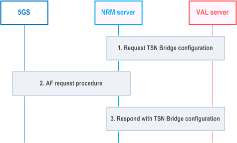
Step 1.
The NRM server receives from the TSN CNC per-stream filtering, policing parameters and related flow information according to IEEE 802.1Q [36] and it uses them to derive TSN QoS information and related flow information. The TSN AF uses this information to identify the DS-TT MAC address of the corresponding PDU session.
Step 2.
NRM server triggers via N5 the AF request procedure as described in TS 23.502 Annex F.2. The AF request includes the DS-TT port MAC address, TSC QoS information, TSC Assistance Information, flow bit rate, priority, Service Data Flow Filter containing flow description including Ethernet Packet Filters.
Step 3.
NRM server responds with a TSN Bridge configuration.