Content for TS 23.501 Word version: 19.0.0
1…
3…
4.2.3
4.2.4
4.2.5…
4.2.8…
4.2.8.2.2
4.2.8.2.3…
4.2.8.4…
4.2.9…
4.2.15…
4.3…
4.3.3
4.3.4
4.3.5
4.4…
4.4.6…
4.4.8…
5…
5.3…
5.3.3…
5.4…
5.5…
5.6…
5.6.7…
5.7…
5.7.2…
5.7.3…
5.7.4
5.7.5…
5.8…
5.8.2.11…
5.9…
5.10…
5.11…
5.15…
5.15.11…
5.16…
5.17…
5.18…
5.19…
5.21…
5.22…
5.27…
5.28…
5.29…
5.30…
5.31…
5.32…
5.32.6…
5.33…
5.34…
5.35…
5.38…
5.43…
6…
6.3…
6.3.8…
7…
7.2…
8…
8.2.4
8.2.5…
8.3…
A…
D…
E…
F
G…
G.3
G.4…
H…
J
K…
M…
N…
O…
P…
8 Control and User Plane Protocol Stacks
8.1 General
8.2 Control Plane Protocol Stacks
8.2.1 Control Plane Protocol Stacks between the 5G-AN and the 5G Core: N2
8.2.2 Control Plane Protocol Stacks between the UE and the 5GC
8.2.3 Control Plane Protocol Stacks between the network functions in 5GC
...
...
8 Control and User Plane Protocol Stacks p. 601
8.1 General p. 601
Clause 8 specifies the overall protocol stacks between 5GS entities, e.g. between the UE and the 5GC Network Functions, between the 5G-AN and the 5GC Network Functions, or between the 5GC Network Functions.
8.2 Control Plane Protocol Stacks p. 601
8.2.1 Control Plane Protocol Stacks between the 5G-AN and the 5G Core: N2 p. 601
8.2.1.1 General p. 601
Following procedures are defined over N2:
- Procedures related with N2 Interface Management and that are not related to an individual UE, such as for Configuration or Reset of the N2 interface. These procedures are intended to be applicable to any access but may correspond to messages that carry some information only on some access (such as information on the default Paging DRX used only for 3GPP access).
-
Procedures related with an individual UE:
- Procedures related with NAS Transport. These procedures are intended to be applicable to any access but may correspond to messages that for UL NAS transport carry some access dependent information such as User Location Information (e.g. Cell-Id over 3GPP access or other kind of User Location Information for Non-3GPP access).
-
Procedures related with UE context management. These procedures are intended to be applicable to any access. The corresponding messages may carry:
- some information only on some access (such as Mobility Restriction List used only for 3GPP access).
- some information (related e.g. with N3 addressing and with QoS requirements) that is to be transparently forwarded by AMF between the 5G-AN and the SMF.
- Procedures related with resources for PDU Sessions. These procedures are intended to be applicable to any access. They may correspond to messages that carry information (related e.g. with N3 addressing and with QoS requirements) that is to be transparently forwarded by AMF between the 5G-AN and the SMF.
- Procedures related with Hand-Over management. These procedures are intended for 3GPP access only.
- The connection of multiple different kinds of 5G-AN (e.g. 3GPP RAN, N3IWF for Un-trusted access to 5GC) to the 5GC via a unique Control Plane protocol: A single NGAP protocol is used for both the 3GPP access and non-3GPP access;
- There is a unique N2 termination point in AMF per access for a given UE regardless of the number (possibly zero) of PDU Sessions of the UE;
- The decoupling between AMF and other functions such as SMF that may need to control the services supported by 5G-AN(s) (e.g. control of the UP resources in the 5G-AN for a PDU Session). For this purpose, NGAP may support information that the AMF is just responsible to relay between the 5G-AN and the SMF. The information can be referred as N2 SM information in TS 23.502 and this specification.
8.2.1.2 5G-AN - AMF p. 602
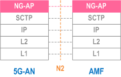
Legend:
8.2.1.3 5G-AN - SMF p. 603
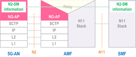
Legend:
- N2 SM information: This is the subset of NG-AP information that the AMF transparently relays between the 5G-AN and the SMF, and is included in the NG-AP messages and the N11 related messages.
8.2.2 Control Plane Protocol Stacks between the UE and the 5GC p. 603
8.2.2.1 General p. 603
A single N1 NAS signalling connection is used for each access to which the UE is connected. The single N1 termination point is located in AMF. The single N1 NAS signalling connection is used for both Registration Management and Connection Management (RM/CM) and for SM-related messages and procedures for a UE.
The NAS protocol on N1 comprises a NAS-MM and a NAS-SM components.
There are multiple cases of protocols between the UE and a core network function (excluding the AMF) that need to be transported over N1 via NAS-MM protocol. Such cases include:
- Session Management Signalling.
- SMS.
- UE Policy.
- LCS.
-
NAS procedures that terminate at the AMF. This includes:
-
Handles Registration Management and Connection Management state machines and procedures with the UE, including NAS transport; the AMF supports following capabilities:
- Decide whether to accept the RM/CM part of N1 signalling during the RM/CM procedures without considering possibly combined other non NAS-MM messages (e.g. SM) in the same NAS signalling contents;
- Know if one NAS message should be routed to another NF (e.g., SMF), or locally processed with the NAS routing capabilities inside during the RM/CM procedures
- Provide a secure NAS signalling connection (integrity protection, ciphering) between the UE and the AMF, including for the transport of payload;
- Provide access control if it applies;
-
Handles Registration Management and Connection Management state machines and procedures with the UE, including NAS transport; the AMF supports following capabilities:
-
It is possible to transmit the other type of NAS message (e.g. NAS SM) together with an RM/CM NAS message by supporting NAS transport of different types of payload or messages that do not terminate at the AMF, i.e. NAS-SM, SMS, UE Policy and LCS between the UE and the AMF. This includes:
- Information about the Payload type;
- Additional Information for forwarding purposes
- The Payload (e.g. the SM message in the case of SM signalling);
- There is a Single NAS protocol that applies on both 3GPP and non-3GPP access. When an UE is served by a single AMF while the UE is connected over multiple (3GPP/Non 3GPP) accesses, there is a N1 NAS signalling connection per access.
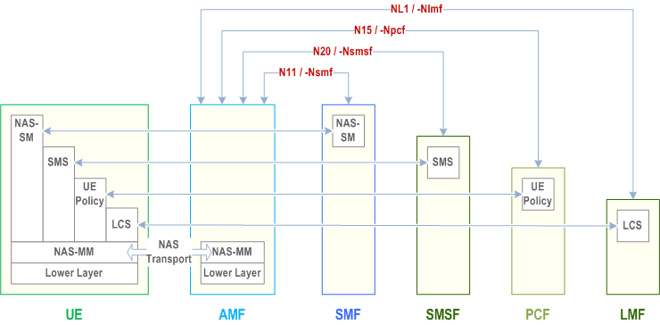
8.2.2.2 UE - AMF p. 605
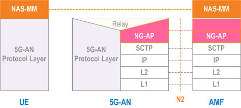
Legend:
- NAS-MM: The NAS protocol for MM functionality supports registration management functionality, connection management functionality and user plane connection activation and deactivation. It is also responsible of ciphering and integrity protection of NAS signalling. 5G NAS protocol is defined in TS 24.501
- 5G-AN Protocol layer: This set of protocols/layers depends on the 5G-AN. In the case of NG-RAN, the radio protocol between the UE and the NG-RAN node (eNodeB or gNodeB) is specified in TS 36.300 and TS 38.300. In the case of non-3GPP access, see clause 8.2.4.
8.2.2.3 UE - SMF p. 605
The NAS-SM supports the handling of Session Management between the UE and the SMF.
The SM signalling message is handled, i.e. created and processed, in the NAS-SM layer of UE and the SMF. The content of the SM signalling message is not interpreted by the AMF.
The NAS-MM layer handles the SM signalling is as follows:
-
For transmission of SM signalling:
- The NAS-MM layer creates a NAS-MM message, including security header, indicating NAS transport of SM signalling, additional information for the receiving NAS-MM to derive how and where to forward the SM signalling message.
-
For reception of SM signalling:
- The receiving NAS-MM processes the NAS-MM part of the message, i.e. performs integrity check, and interprets the additional information to derive how and where to derive the SM signalling message.
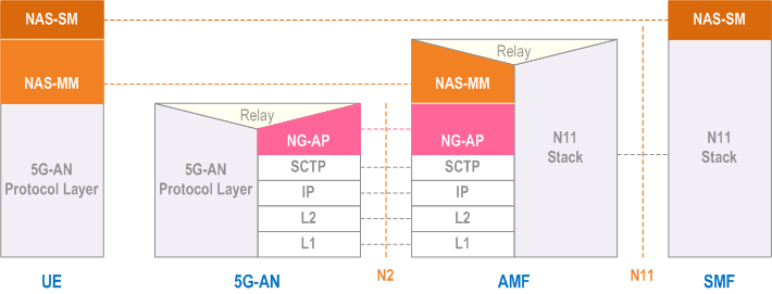
Legend:
- NAS-SM: The NAS protocol for SM functionality supports user plane PDU Session Establishment, modification and release. It is transferred via the AMF, and transparent to the AMF. 5G NAS protocol is defined in TS 24.501
8.2.3 Control Plane Protocol Stacks between the network functions in 5GC p. 606
8.2.3.1 The Control Plane Protocol Stack for the service based interface p. 606
The control plane protocol(s) for the service-based interfaces listed in clause 4.2.6 is defined in the TS 29.500
8.2.3.2 The Control Plane protocol stack for the N4 interface between SMF and UPF p. 606
The control plane protocol for SMF-UPF (i.e. N4 reference point) is defined in TS 29.244.