Content for TS 23.501 Word version: 19.0.0
1…
3…
4.2.3
4.2.4
4.2.5…
4.2.8…
4.2.8.2.2
4.2.8.2.3…
4.2.8.4…
4.2.9…
4.2.15…
4.3…
4.3.3
4.3.4
4.3.5
4.4…
4.4.6…
4.4.8…
5…
5.3…
5.3.3…
5.4…
5.5…
5.6…
5.6.7…
5.7…
5.7.2…
5.7.3…
5.7.4
5.7.5…
5.8…
5.8.2.11…
5.9…
5.10…
5.11…
5.15…
5.15.11…
5.16…
5.17…
5.18…
5.19…
5.21…
5.22…
5.27…
5.28…
5.29…
5.30…
5.31…
5.32…
5.32.6…
5.33…
5.34…
5.35…
5.38…
5.43…
6…
6.3…
6.3.8…
7…
7.2…
8…
8.2.4
8.2.5…
8.3…
A…
D…
E…
F
G…
G.3
G.4…
H…
J
K…
M…
N…
O…
P…
P Personal IoT Networks
P.1 PIN Reference Architecture
P.2 Session management and traffic routing for PIN
Q Satellite coverage availability information
R 5GS support for Indirect Network Sharing deployment
R.1 General
$ Change history
P Personal IoT Networks |R18| p. 677
P.1 PIN Reference Architecture p. 677
Figure P.1-1 shows the logical Personal IoT Network (PIN) reference architecture.
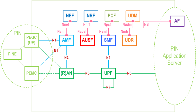
A PIN consists of one or more devices providing gateway/routing functionality known as the PEGC to route the traffic towards the 5G network, and one or more devices providing PIN management functionality known as the PEMC to manage the PIN; and device(s) enabling communication within the PIN called the PINE. A PINE and PEMC can be a non-3GPP device.
The PIN can also have an AF for PIN (see TS 23.542). The AF for PIN can be deployed by mobile operator or by an authorized third party. When the AF for PIN is deployed by third party, the interworking with 5GC is performed via the NEF.
With PIN-DN communication, the PEMC and PEGC communicates with the AF for PIN at the application layer over the user plane. The PEGC and PEMC can communicate with each other via PIN direct communication using 3GPP access (e.g. PC5) or non-3GPP access (e.g. WiFi, BT) or via PIN indirect communication using a PDU Session in the 5GS.
P.2 Session management and traffic routing for PIN p. 677
The general session management principles as described in clause 5.6, the QoS model as defined in clause 5.7 and the User Plane management for 5GS as defined in clause 5.8 are applicable to PIN-DN communication and PIN indirect communication.
If a PIN has multiple PEGCs, 5G VN group communication mechanisms can be used for PIN indirect communication. In this case a dedicated SMF set is used for managing the PIN related PDU Sessions from all the PEGCs of that PIN and the PDU session management principles for 5G VN-LAN-type services as specified in clause 5.29.3 are applicable. The user plane handling for 5G LAN-type services as specified in 5.29.4 are applicable with following differences:
- For PIN indirect communication N19-based traffic forwarding is not used i.e. the PIN traffic is forwarded using:
- N6-based traffic forwarding method, where the UL/DL traffic for the PIN communication is forwarded to/from the DN;
- local switching as depicted in Figure P.2-1 below, following the principles of local switching of traffic for 5G VN LAN-type service.
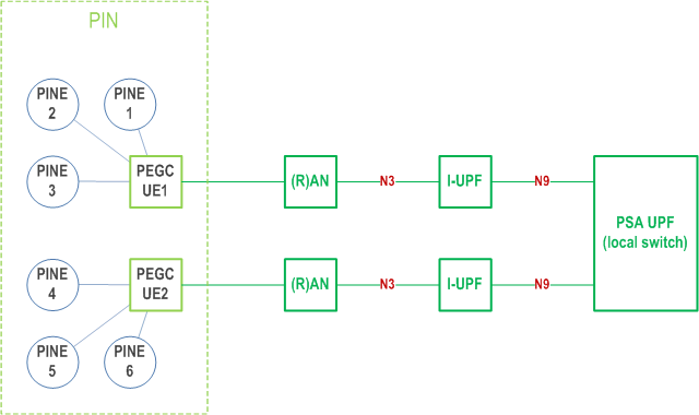
The SMF configures the UPF(s) to apply N6-based traffic forwarding to route traffic between PDU Sessions of different PEGCs of a PIN as specified in clause 5.8.2.13. The SMF can apply local switching as specified in clause 5.8.2.13 in order to enable UPF locally forward uplink stream from one PDU session of one PEGC of a PIN as downlink stream of PDU session of one or more PEGC(s) of the same PIN. For local switching of PIN traffic between PIN related PDU sessions from different PEGCs of a single PIN, based on the (DNN, S-NSSAI) combination that is used for the PDU session related to PIN, the SMF provides a Network Instance to the UPF in FAR and/or PDR via N4 Session Establishment/Modification procedures.
Q Satellite coverage availability information |R18| p. 679
The protocol and format of satellite coverage availability information to be provisioned to the UE via PDU session or SMS is not defined in this release of the specification, but this annex provides some examples on the information that constitutes input to the source of satellite coverage availability information e.g. external server and the output it provides to the UE. Satellite coverage availability information can be indicated to the UE by indications corresponding to whether or not coverage is available for a specific satellite RAT Type for a particular location and time, where:
- These indications can be Boolean "True" (e.g. coverage available) and "False" (coverage not available);
- locations can correspond to grid points in a fixed array (e.g. rectangular, hexagonal);
- Coverage availability times may occur at fixed periodic intervals; and
- Coverage availability information is per RAT Type. The information provisioned to the UE can include coverage information on only one PLMN or multiple PLMNs.
- Serving PLMN ID (if not already known or implied).
- One or more satellite RAT Types (where satellite coverage availability information is then expected for these one or more RAT Types).
- List of supported satellite frequency bands (if not implied by the particular RAT Types).
- Present UE location (e.g. latitude and longitude) for a reference grid point (e.g. the most Southerly and then most Westerly grid point).
- Type of Array (e.g. rectangular or hexagonal).
- Minimum elevation angle.
Satellite coverage availability information at a given grid point = <N> <Binary 0 or 1><Duration 1> <Binary 0 or 1><Duration 2> . . . . <Binary 0 or 1><Duration N>
The above would be concatenated for all of the grid points to produce the satellite coverage availability information.
When SMS is used to deliver the satellite coverage availability information, the UE input and satellite coverage availability information output can be delivered in a series of concatenated SMS messages using possibly the same format.
R 5GS support for Indirect Network Sharing deployment |R19| p. 680
R.1 General p. 680
This annex provides guidance on how 5GS features and capabilities can be used to support Indirect Network Sharing deployment option which is specified in clause 6.21 of TS 22.261.
The Indirect Network Sharing deployment option is described in clause 5.18 and further illustrated in the Figure 5.18.1-2.
In geographical areas with Indirect Network Sharing deployment the existing mobility restriction mechanisms specified in clause 5.3.4.1 can be applied. This can be controlled by subscription data not dedicated to Indirect Network Sharing and Indirect Network Sharing policies in AMF of the hosting network.
For the mobility management, the related procedures (e.g. handover, mobility registration update) specified in clause 4.23 of TS 23.502 can be reused.
$ Change history p. 681
![]()
![]()