Content for TS 23.501 Word version: 19.0.0
1…
3…
4.2.3
4.2.4
4.2.5…
4.2.8…
4.2.8.2.2
4.2.8.2.3…
4.2.8.4…
4.2.9…
4.2.15…
4.3…
4.3.3
4.3.4
4.3.5
4.4…
4.4.6…
4.4.8…
5…
5.3…
5.3.3…
5.4…
5.5…
5.6…
5.6.7…
5.7…
5.7.2…
5.7.3…
5.7.4
5.7.5…
5.8…
5.8.2.11…
5.9…
5.10…
5.11…
5.15…
5.15.11…
5.16…
5.17…
5.18…
5.19…
5.21…
5.22…
5.27…
5.28…
5.29…
5.30…
5.31…
5.32…
5.32.6…
5.33…
5.34…
5.35…
5.38…
5.43…
6…
6.3…
6.3.8…
7…
7.2…
8…
8.2.4
8.2.5…
8.3…
A…
D…
E…
F
G…
G.3
G.4…
H…
J
K…
M…
N…
O…
P…
A Relationship between Service-Based Interfaces and Reference Points
B Mapping between temporary identities
C Guidelines and Principles for Compute-Storage Separation
...
...
A Relationship between Service-Based Interfaces and Reference Points p. 612
Service-Based Interfaces and Reference Points are two different ways to model interactions between architectural entities. A Reference Point is a conceptual point at the conjunction of two non-overlapping functional groups (see TR 21.905). In Figure A-1 the functional groups are equivalent to Network Functions.
A reference point can be replaced by one or more service-based interfaces which provide equivalent functionality.
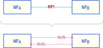
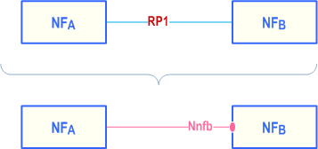
Reference points exist between two specific Network Functions. Even if the functionality is equal on two reference points between different Network Functions there has to be a different reference point name. Using the service-based interface representation it is immediately visible that it is the same service-based interface and that the functionality is equal on each interface.
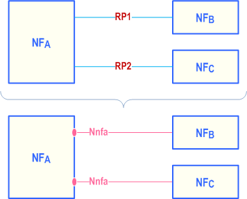
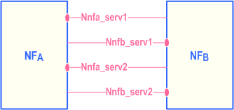
A NF may expose one or more services through Service based interfaces.
B (Normative) Mapping between temporary identities p. 614
When interworking procedures with N26 are used and the UE performs idle mode mobility from 5GC to EPC the following mapping from 5G GUTI to EPS GUTI applies:
- 5G <MCC> maps to EPS <MCC>
- 5G <MNC> maps to EPS <MNC>
- 5G <AMF Region ID> and 5G <AMF Set ID> maps to EPS <MMEGI> and part of EPS <MMEC>
- 5G <AMF Pointer> map to part of EPS <MMEC>
- 5G <5G-TMSI> maps to EPS <M-TMSI>
C Guidelines and Principles for Compute-Storage Separation p. 615
5G System Architecture allows any NF/NF Service to store and retrieve its unstructured data (e.g. UE contexts) into/from a Storage entity (e.g. UDSF) as stated in clause 4.2.5 in this release of the specification. This clause highlights some assumptions, principles regarding NF/NF services that use this Storage entity for storing unstructured data:
- It is up to the Network Function implementation to determine whether the Storage entity is used as a Primary Storage (in which case the corresponding context stored within the NF/NF Service is deleted after storage in the Storage entity) or the Storage entity is used as a Secondary Storage (in which case the corresponding context within the NF/NF Service is stored).
- It is up to the NF/NF Service implementation to determine the trigger (e.g. at the end of Registration procedure, Service Request procedure etc) for storing unstructured data (e.g. UE contexts) in the Storage entity but it is a good practice for NF/NF service to store stable state in the Storage entity.
- Multiple NF/NF service instances may require to access the same stored data in the Storage entity (e.g. UE context), around the same time, then the resolution the race condition is implementation specific.
- All NFs within the same NF Set are assumed to have access to the same unstructured data stored within the Storage entity.
- AMF planned removal with UDSF (clause 5.21.2.2.1) and AMF auto-recovery (with UDSF option in clause 5.21.2.3) assume that a storage entity/UDSF is used either as a primary storage or secondary storage by the AMF for storing UE contexts.
- It is up to implementation of the Storage entity to make sure that only NFs that are authorized for a certain data record can access this data record.
![]()
![]()
![]()