Content for TR 22.867 Word version: 18.2.0
1…
5…
5.2…
5.3…
5.4…
5.5…
5.7…
5.8…
5.10…
5.12…
5.13…
5.15…
5.16…
5.17…
5.18…
5.20…
5.22…
5.23…
6…
8…
5.12 Distribution Intelligence - FLISR (Fault Location, Isolation, and Service Restoration)
5.12.1 Overview
5.12.2 Feeder automation
5.12.3 High speed current differential protection
...
...
5.12 Distribution Intelligence - FLISR (Fault Location, Isolation, and Service Restoration) p. 49
5.12.1 Overview p. 49
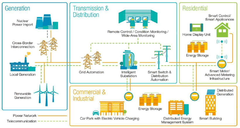
"Distribution intelligence" refers to the part of the Smart Grid that applies to the distribution system, that is, the wires, switches, and transformers that connect the utility substation to the customers. A key component of distribution intelligence is outage detection and response. Today, many utility companies rely on customer phone calls to know which areas of their distribution system are being affected by a power outage. Along with smart meters, distribution intelligence will help to quickly pinpoint the source of a power outage so that repair team can be immediately dispatched to the problem area. Most utility companies count on complex power distribution schemes and manual switching to keep power flowing to most of their customers, even when power lines are damaged and destroyed. However, this approach has its limitations, and in many cases an automated system could respond more quickly and could keep the power flowing to more customers. By having sensors that can indicate when parts of the distribution system have lost power, and by combining automated switching with an intelligent system that determines how best to respond to an outage, power can be rerouted to most customers in a matter of seconds, or perhaps even milliseconds.

The automation in distribution with self-healing solutions is surely a critical challenge to consider in this transformational evolution towards Smart/Smarter Energy. Self-healing will enable system operators to benefit from a significant reduction in the outage duration and number of affected customers, which reacts quickly and precisely to power disturbances so that only those in the immediate neighbourhood are affected, while avoiding any interruption in power. Self-healing not only acts against grid disturbances, but secures the grid against disturbances spread. The basic requirements include [18]:
- Fast and proper detection of grid disturbances.
- Redistribution of grid resources to avoid adversative impacts.
- Assuring the continuity of service under any conditions.
- Minimization of service restoration time.
- feeder automation
- line current differential protection
5.12.2 Feeder automation p. 50
5.12.2.1 Description p. 50
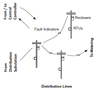
Feeder automation is designed to utilise controller devices that are especially designed to support the self-healing of power distribution grids with overhead lines. The self-healing logic resides in individual controller devices located at the poles at the feeder level. Using peer-to-peer communication (e.g. via IEC 61850 GOOSE) among the controller devices, the system operates autonomously without the need of a regional controller or control centre. All self-healing steps carried out are reported immediately to the control centre to keep the grid status up-to-date.

5.12.2.2 Pre-condition p. 50
The controller devices have been mounted, connected, and configured during commissioning and deployment. The configuration is usually not done via the mobile network but via local wired connection.
The controller devices are connected to the 5G network, and the peer-to-peer communication is enabled using IEC 61850 GOOSE (OSI Layer 2, broadcast/subscription Ethernet-based protocol).
5.12.2.3 Service flow p. 50
Communications are enabled via 5G network among the controller devices
- among controller devices serving the same feeder and
- among the controller devices of the whole area and the control centre.
5.12.2.4 Post-condition p. 51
5G communication runs and power distribution is restored in the affected area.
5.12.2.5 Existing features partly or fully covering the use case functionality p. 51
The use case "Distributed automated switching for isolation and service restoration" has been captured in TS 22.104 Annex A.4.4.1, while the corresponding performance requirements have been specified in Table 5.2-1 "Periodic deterministic communication service performance requirements":
| Characteristic parameter | Influence quantity | Remarks | ||||||||
|---|---|---|---|---|---|---|---|---|---|---|
| Communication service availability: target value (note 1) | Communication service reliability: mean time between failures | End-to-end latency: maximum (notes 2, 5) | Service bit rate: user experienced data rate (note 5) | Message size [byte] (note 5) | Transfer interval: target value (note 5) | Survival time (note 5) | UE speed (note 6) | # of UEs | Service area (note 3) | |
| 99.9999 % | - | < 5 ms | 1 kbit/s (steady state) 1.5 Mbit/s (fault case) | < 1500 | < 60 s (steady state) ≥ 1 ms (fault case) | transfer interval | stationary | 20 | 30 km x 20 km | Electrical Distribution - Dis-tributed automated switching for isolation and service restoration (A.4.4); (note 4) |
|
NOTE 1:
One or more retransmissions of network layer packets may take place in order to satisfy the communication service availability requirement.
NOTE 2:
Unless otherwise specified, all communication includes 1 wireless link (UE to network node or network node to UE) rather than two wireless links (UE to UE).
NOTE 3:
Length x width (x height).
NOTE 4:
Communication includes two wireless links (UE to UE).
NOTE 5:
It applies to both UL and DL unless stated otherwise.
NOTE 6:
It applies to both linear movement and rotation unless stated otherwise.
|
||||||||||
The gaps identified include:
5.12.2.6 Potential New Requirements needed to support the use case p. 52
[PR.5.12.2-001]
The 5G system shall be able to provide a periodic deterministic communication with the service performance requirements reported in the tables below.
| Communication service availability | Max Allowed End-to-end latency (note 1) | Message size [byte] | UE speed | # of UEs | Service Area |
|---|---|---|---|---|---|
| > 99.999 % | 20 ms | < 100 | Stationary | ≤ 100/km² | several km² |
|
NOTE 1:
UE to UE communication.
|
|||||
| Number of devices in one Communication group for clock synchronisation | 5GS synchronicity budget requirement | Service area |
|---|---|---|
| ≤ 100/km² | ≤ 10 μs | several km² |
5.12.3 High speed current differential protection p. 52
5.12.3.1 Description p. 52
The high speed current differential protection for smart energy distribution systems is capable of sub-millisecond fault detection. The approach utilises the natural characteristics of differential current measurements to significantly reduce fault detection times, which has been described in detail in clause 5.4. This use case focuses on the traffic characteristics.
5.12.3.2 Pre-condition p. 52
Protection relays (e.g. relay_a and relay_b in Figure 5.4.1-1) are deployed and switched on in the distribution grid. All relays are connected to the 5G network and are synchronised with neighbouring relays in the distribution grid with a precision of <10 μs to ensure that the current values are sampled at the same time.
5.12.3.3 Service flow p. 52
The protection relays exchanges the current samples via the 5G system. Each relay then compares the sent and received samples to determine if a fault has occurred in a protected area in order to isolate the fault. The detail of fault detection can be found in clause 5.4.
The sampling rate varies dependent on the algorithms designed by the manufacturers. A protection relay collects the current samples (with the typical message size of up to 245 bytes) at a frequency in the range of [600, 1200, 1600, 3000] Hz. The exchange of measurement samples is done in a strictly cyclic and deterministic manner. [6] [20] With the sampling rate of 600 Hz (6 times per 10 ms), the transfer interval would be 1,667 ms with the required bandwidth of 1.18 Mbit/s; for 1200 Hz (12 times per 10 ms), the transfer interval would be 0,833 ms with the required bandwidth of 2.36 Mbit/s.
As to the latency, as pointed out in clause 5.4 the maximum allowed end-to-end delay between two protection relays would be between 5ms and 10ms depending on the voltage levels as specified in IEC 61850-90-1 [6]. For some legacy systems the latency usually is set to 15ms [20].
5.12.3.4 Post-condition p. 52
5G communication runs and power distribution is restored in the affected area.
5.12.3.5 Existing features partly or fully covering the use case functionality p. 53
The use case "Application of differential protection in distribution Network of Smart Grid" has been captured in TR 22.804. However the use case and the associated service requirements are missing in TS 22.104.
The missing requirements based on differential protection in distribution network need to be captured.
5.12.3.6 Potential New Requirements needed to support the use case p. 53
[PR.5.12.3-001]
The 5G system shall be able to provide periodic deterministic communication with the service performance requirements reported in the Tables below.
| Communication service availability | End-to-end latency: maximum (note 1) | Service bitrate: user experienced data rate | Message size [byte] | Transfer interval: target value | Survival time | UE speed | # of UEs | Service area | |
|---|---|---|---|---|---|---|---|---|---|
| > 99.999 % | 15 ms | 2.5 Mbit/s | < 245 | ≤ 1 ms | transfer interval (one frame loss) | stationary | ≤ 100/km² | several km² | |
| > 99.999 % | 15 ms | 1.2 Mbit/s | < 245 | ≤ 2 ms | transfer interval (one frame loss) | stationary | ≤ 100/km² | several km² | |
| > 99.999 % | 10 ms | 2.5 Mbit/s | < 245 | ≤ 1 ms | transfer interval (one frame loss) | stationary | ≤ 100/km² | several km² | |
| > 99.999 % | 10 ms | 1.2 Mbit/s | < 245 | ≤ 2 ms | transfer interval (one frame loss) | stationary | ≤ 100/km² | several km² | |
| > 99.999 % | 5 ms | 2.5 Mbit/s | < 245 | ≤ 1 ms | transfer interval (one frame loss) | stationary | ≤ 100/km² | several km² | |
| > 99.999 % | 5 ms | 1.2 Mbit/s | < 245 | ≤ 2 ms | transfer interval (one frame loss) | stationary | ≤ 100/km² | several km² | |
|
NOTE 1:
UE to UE communication.
|
|||||||||
| Number of devices in one Communication group for clock synchronisation | 5GS synchronicity budget requirement | Service area |
|---|---|---|
| ≤ 100/km² | ≤ 10 μs | several km² |