Content for TR 22.867 Word version: 18.2.0
1…
5…
5.2…
5.3…
5.4…
5.5…
5.7…
5.8…
5.10…
5.12…
5.13…
5.15…
5.16…
5.17…
5.18…
5.20…
5.22…
5.23…
6…
8…
5 Use cases p. 14
5.1 Use case of Distributed Energy Storage p. 14
5.1.1 Description p. 14
Distributed energy includes various forms such as solar energy, wind energy, fuel cell and gas combined. It is generally distributed in the user site, or near locations to realize energy generation, storage and supply. Distributed energy system has the characteristics of flexible location and decentralization, which adapts well to decentralized energy demand, and has reduced the huge investment required for upgrading the transmission and distribution power grid. It also works as a backup for the large power grid to improve reliability of whole energy supply. In storms, ice and snow weather, when the large power grid is severely damaged, distributed energy sources can form islands or microgrids on their own to provide emergency energy to important users such as hospitals, transportation hubs, radio and television.
But the distributed energy system has brought new technical problems and challenges to the power grid operation. When the distributed energy is connected to the large power grid, the energy flow on the distributed power grid becomes more complicated for that the user is becoming both the electricity user and the generator, and the current presents two-way flow and real-time dynamic changes. To improve the reliability, flexibility and efficiency of the distributed power grid, the communication system with a low latency, high reliability, massive connections and a high data rate is considered.
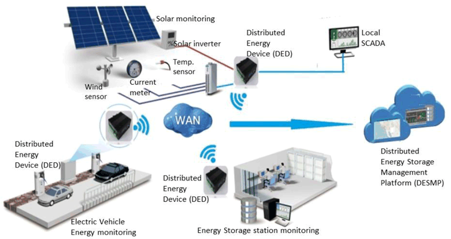
Figure 5.1.1-1: Example of Distributed Energy Storage grid architecture
(⇒ copy of original 3GPP image)
(⇒ copy of original 3GPP image)
Seeing Figure 5.1.1-1, it is one example of Distributed Energy storage grid architecture. The distributed power grid which is comprised of residential, commercial and light storage users, requires to exchange information among the Distributed Energy Storage Management Platform (DESMP) and the diverse Distributed Energy Devices (DED). The information exchanged in the distributed energy grid is not only to collect energy related data, but also to coordinate working flows of the distributed energy storage equipment, to change the equivalent load characteristics, and to realize flexible energy grid through load interaction etc.
The DED is plug-and-play and periodically collects the operating information, such as battery energy, charge and discharge energy, alarm information, etc., and transfers them to DESMP. The DESMP regularly maintains connections with the DED and determines the online status and issue instructions to the DED to control the switch of the device and set the energy etc. Further, it obtains the electricity, energy, load and other information of the grid-connected users in the area from the DED to support the decision-making of flexible interaction between the distributed energy storage and the large power grid, or to analyze the user's electricity habits to guide the operation of distributed energy storage.
5.1.2 Pre-conditions p. 15
Distributed energy system has the following functions: data acquisition and processing, active power adjustment, voltage and reactive power control, island detection, dispatch and coordination control, etc. It is mainly composed of DESMP, the DED and communication system.
The DESMP is located in region center. And the diverse DED can be deployed in buildings, indoors, outdoors, tunnels, ports and electric vehicles which may be faced a poor communication signal condition or even out of network coverage.
The 5G system connects the DEDs with the DESMP.
5.1.3 Service Flows p. 15
Every time after the DED and the DESMP establish a communication connection, the DED reports its configuration data to DESMP. For reliability, in general, the communications between DESMP and DED should be supported by multiple connections and backup each other.
The heartbeat data is always transmitted between the DESMP and DED to maintain a normal connection.
In the process of general service flow, there are three kinds of data exchange:
- Command delivering: DESMP sends control commands to the DED. It always requires <10ms latency with 99.9% reliability communication service for control frequency, power etc.
- Data reporting: equipment normal operation information, mainly including energy storage battery, energy storage converter, AC and DC charging and discharging equipment and other current operating data. It always requires <1s latency.
- Other data: For example, the DED actively requests data, such as requesting the electricity price information from DESMP, and the AC/DC charging and discharging facility sends relevant information about the current charging and discharging under abnormal conditions.
Case 1: data collection for energy storage in rural area
In the typical scenario of energy storage in rural area, it is always a large energy storage in one location. Considering the data collection, taking 100Ah lithium iron phosphate batteries as an example, the integration of a 2MWh energy storage container requires 6,250 batteries. So there are 6250 voltage and temperature collection points, and 780 current collection points, plus other 12-bit data e.g. alarms, internal auxiliary equipment such as air-conditioning, environmental monitoring and video. The collection data for the 2 MWh energy storage container is about 20,000 16-bit data and among them, the current related collection points is about 800, which need implement collection every millisecond and report every 10 ms, other 13000 points need implement collection and report every second.
Thus, there are at least two traffic models (except video) in the typical 100MWh energy storage station which is constructed by 50 2MWh energy storage containers. One is for current flow with (800*50=40000) collection 16-bit data per millisecond, and every 10ms, the UL reported data volume is (40000*2*10=800 kbyte/10ms) which data rate is 640Mbit/s. The others are (13000*50=650000) collection 16-bit data per second, and every second, the UL reported data volume is (650000*2=1300 kbyte/s) which data rate is 10.4 Mbit/s.
Besides above, the surveillance video is the third kind of collected data. In every storage container, the typical video data is 12.5 Mbytes for every second. And in one energy storage station, there need 50 storage containers. Thus, the UL data rate per storage station is up to 12.5 Mbytes/s * 50(containers) * 8 = 5 Gbit/s.
Case 2: data collection for distributed energy storage in urban area
Virtual energy storage (VES) is a new type of energy storage system formed by the aggregation of user side power loads (such as air conditioning, refrigeration, heating, electric vehicles, etc.) with certain adjustment capabilities. [2]
In urban area scenario, electric vehicle is one type of VES element. It is a trend that the DED will be installed in the electric vehicle not only in the charging pole.
For electric vehicle, it is generally installed with about 7000 batteries which requires 7000 voltages, about 1000 current & temperature collection points at least. Further considering other collected data such as electronic control, charging and vehicle-grid interaction, for one electric vehicle, there is total about 10,000 16-bit data and among them, the current related collection data is more than 1000 16-bit data which need to be collected every millisecond and reported every 10ms, the others is more than 8000 16-bit data which need to be collected and reported every second.
So, there are also at least two traffic models in this case, one is the current model, every 10 ms, the UL reported data volume is (1000*2*10=20 kbytes) which data rate is 16 Mbit/s. The other is reported every second and the data volume is (8000*2=16 kbytes/s) which data rate is 128 kbit/s.
5.1.4 Post-conditions p. 16
In urban public building, community, industrial park, rural village, this kind of distributed energy storage system with the help of 5G system works well and can supply reliable power for users.
5.1.5 Existing features partly or fully covering the use case functionality p. 16
The 5G system shall be able to provide required communication service for distributed power storage where it is indoor, outdoor, underground etc.
When required by regulations, the 5G system shall be able to utilize dedicated communication resource including core network and radio network to support physical isolation communication service for energy applications.
5.1.6 Potential requirements p. 16
[PR.5.1-001]
The 5G system shall be able to provide required communication service for distributed energy storage according to the KPIs given in Table 5.1.6-1 and Table 5.1.6-2.
| scenario | use case | transfer interval target value
(ms) |
message size
(byte) |
data rate per storage location
(bit/s) (note 1) |
communication latency (ms) | reliability | storage node density # /km²
(note 2) |
active factor/ km² (note 3) |
|---|---|---|---|---|---|---|---|---|
| Dense Urban | Virtual energy storage monitoring | UL: 10 | UL:>20k | UL: >16 M DL: >100 k | DL:10 UL:10 | DL: >99.90% | >1k | 10% |
| Virtual energy storage: other data collection | UL: 1000 | UL: 16k DL: >100k | UL: >128 k DL: >100 k | DL:<10 UL:<1000 | DL: >99.90% | >1k | 10% | |
| Rural | Power storage station monitoring | UL: 10 | UL: 16k*50 | UL: > 640 M DL: > 100 k | DL:<10 UL:<10 | DL: >99.90% | >100 | 10% |
| Energy storage station operation data collection: other data | UL: 1000 | UL: 26k*50 DL: >100k | UL: > 10.4 M DL: > 100 k | DL:<10 UL:<1000 | DL: >99.90% | >100 | 10% | |
|
NOTE 1:
This KPI is to require data rate in one Energy storage station which may via one or more 5G connections and via one or more 3GPP UE(s) at the same time.
NOTE 2:
It is used to deduce data volume in an area which has multiple energy storage stations. The data volume can be deduced through follow formula: (Current + other data) data rate per storage station * (Storage node density /km²) * (Active factor/km²) + video data rate per storage station * (Storage node density /km²)
NOTE 3:
Active factor means the proportion that the number of active DED which are delivering its collected data during one second time window compared with whole number of DED in the area which has multiple energy storage station
|
||||||||
| scenario | use case | data rate per storage station (bit/s) (note 1) | communication latency (ms) | reliability | storage node density # / km² | ||||
|---|---|---|---|---|---|---|---|---|---|
| Rural | Energy storage station: video | UL: >5 G DL: >100 k | DL:<10 UL:<1000 | DL: >99.90% | >100 | ||||
|
NOTE 1:
The data rate is to require data rate in one Energy storage station which may via one or more 5G connections and one or more 3GPP UE(s) at the same time. It can be calculated with following formula: 12.5 Mbytes/s * 50(containers) * 8 = 5 Gbit/s
|
|||||||||
![]()
![]()
![]()