Content for TR 22.867 Word version: 18.2.0
1…
5…
5.2…
5.3…
5.4…
5.5…
5.7…
5.8…
5.10…
5.12…
5.13…
5.15…
5.16…
5.17…
5.18…
5.20…
5.22…
5.23…
6…
8…
5.2 Use case of advanced metering
5.2.1 Description
5.2.2 Pre-Conditions
5.2.3 Service Flows
5.2.4 Post-Conditions
5.2.5 Existing features partly or fully covering the use case functionality
5.2.6 Potential New Requirements needed to support the use case
...
...
5.2 Use case of advanced metering p. 17
5.2.1 Description p. 17
Instead of recording and sending the metering data from a traditional wired electricity meter unit, electricity metering collecting can be executed by an UE integrated smart meter unit Smart meter units can send real-time metering data to the server in the Power Enterprise through mobile networks. In this way, the Power Enterprise based on the analysis of the user's power consumption behavior give users more scientific and reasonable power consumption suggestions, to develop users' power consumption and energy-saving habits. This is also a possible usage of AMI.
Advanced Metering utilizes AMI (Advanced Meter Infrastructure) system to collect, count, analyze, distribute and manage abnormal electrical energy data in the generation, transmission, distribution and using stages. It can collect real-time data of user power, monitor line loss, and power outage, real-time identify the change of household, calculate of three-phase imbalance, and monitor station voltage.
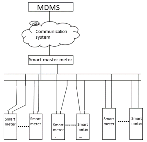
The AMI is usually comprised of smart meter, concentrator, two-way communication network, measurement data management system (MDMS), and an optional user indoor network (HAN). See Figure 5.2.1-1.

In general, the electric smart meter co-works with MDMS to deliver and perform control command for measuring instruments. The electric smart meters monitor relevant user energy status and deliver these data through concentrator to MDMS. The MDMS sends control commands according to its policy and status data collected. The remote commands from the MDMS include: tripping, closing permission, alarm, alarm release, power protection, power protection release.
Accurate Fee control is one of the basic service of advanced metering, when the user owes the fee or there is an emergency, it should be able to cut off or restore power supply in time, as the operation involves the safety& QoE of power users, a real-time response is required.
For the advanced metering application, the application layer through the communication protocol to encrypt and protect these key data, in order to protect all data, at least logical isolation is required, physical isolation is better.
Due to massive electricity meter boxes and household appliances keep online at the same time, the amount of connections the mobile network maintains simultaneously is so enormous that challenging to the mobile network capacity. It is estimated that the increased connections will up to 50-100 times.
5.2.2 Pre-Conditions p. 18
SS is a power company and it constructs AMI system to deploy advanced meter service for its users. Operator TT has a contract with the power company SS to supply communication service for the AMI system.
Tom is one of the user of SS. In his house, all the electric equipment's energy data can be collected by smart meter and then reported to the MDMS of SS.
The smart meter is located in Tom's house or nearby and the MDMS is located in the remote city center. The distance between the smart meter and the energy management center can be as far as a middle size city range (e.g. Tens of km).
Peter is another user of SS. He has a contract with SS about smart energy usage in his house. SS provides electrical sockets with metering function for typical electrical appliances in his house and all the electrical energy generated by typical electrical appliances that from the electrical socket is measured in real time.
5.2.3 Service Flows p. 18
Scenario 1:
- The smart meter in Tom's house report related energy usage data to SS.
- The MDMS of SS sends commands to smart meter in Tom's home to adjust smart meter report frequency and content considering its whole energy working status.
- The smart meter in Tom's home changes the report scheme accordingly.
- When the MDMS detects that the user's remaining electricity will be run out, it will send an alarm command to remind the user to recharge as soon as possible;
- When the user's remaining electricity is exhausted, the MDMS will issue a trip command and the smart meter need implement the trip action accordingly which requires the latency less than 200ms (command delivery + command action);
- When there are special circumstances that cannot be cut off, the MDMS can issue a power protection command in advance to ensure that the smart meter will not trip for related circumstances.
Scenario 2:
- After the smart meter in Tom's house reports the status data to the MDMS, it detects that something is wrong with Tom's home electricity supply system.
- The MDMS asks the smart meter to report more information for troubleshooting.
- The smart meter co-works with MDMS to resolve the problem.
Scenario 3:
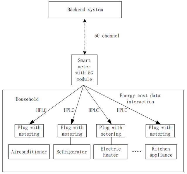
The smart energy meter works as a home gateway, and every electric equipment with metering functions is connected and interacted with the smart energy meter through HPLC (high-speed power line carrier) or 5G. The Figure 5.2.3-1 illustrates the typical scenario.
The electricity consumption information of various smart household appliances is delivered to the smart energy meter. Then the smart energy meter uploads them to backend platform through 5G system. These information are user private data and require physical isolation delivery with other application data.

- The socket measures energy data in real time and deliver it to the smart energy meter. The communication link between them can be HPLC (High-speed power line carrier) or 5G.
- The smart energy meter acting as a data gateway can receive all the energy data in Peter's house and send them to the backend platform of SS.
- According to the actual load of the energy grid, SS has the possibility to adjust user's energy usage in real time. For example, when the energy is overload, the backend platform sends control command to adjust the temperature of the air conditioner in Peter's house; when the energy load is reduced, it can encourage users to use more energy such as electric vehicle charging.
5.2.4 Post-Conditions p. 20
The energy related information from electric equipment can be reported to the MDMS on demand with required content and required communication performance.
The electric accurate fee control function can be implemented.
Co-working with smart meter, the MDMS can remotely troubleshoot energy problem for its user.
The power grid company regularly provides users with detailed energy consumption analysis reports based on the collected data, and guides users to use electricity scientifically and rationally.
5.2.5 Existing features partly or fully covering the use case functionality p. 20
The 5G system shall be able to support resilience to dynamic adjust connection service performance considering advanced metering demand.
The 5G system shall be able to provide connection service wherever indoor, outdoor, low and medium altitude for advanced metering applications.
The 5G system shall be able to support at least logical isolation communication service for advanced meter applications.
The 5G IoT device shall be able to connect energy equipment via 3GPP/non-3GPP connections to get energy data and to deliver the data to back-end energy applications via 5G connection.
5.2.6 Potential New Requirements needed to support the use case p. 20
[PR.5.2-001]
The 5G system shall be able to provide required communication service for advanced metering application according to KPI given in Table 5.2.6-1.
| User experienced data rate
(bit/s) |
Latency
(ms) |
Reliability
% |
Connection density | Coverage | |||||
|---|---|---|---|---|---|---|---|---|---|
| UL:<2M DL:<1M | Accuracy fee control: < 100 (note 2); General information data collection: <3000 | >99.99 | <10000/km² (note 3) | N/A | |||||
|
NOTE 1:
The KPI values refer [66].
NOTE 2:
The accuracy fee control latency here is for communication one way latency from 5G IoT device to backend system while the distance between them is no more than 40 km i.e. city range. The command implementation needs 100 ms.
NOTE 3:
It is the typical connection density in today city environment. With the evolution from meter centralization collection to sockets in home directly collection, the connection density is expected to increase 5-10 times.
|
|||||||||