Content for TR 22.867 Word version: 18.2.0
1…
5…
5.2…
5.3…
5.4…
5.5…
5.7…
5.8…
5.10…
5.12…
5.13…
5.15…
5.16…
5.17…
5.18…
5.20…
5.22…
5.23…
6…
8…
8 Conclusion and recommendations
A Underground 3GPP Access
A.1 Description
A.2 Pre-conditions
A.3 Service Flows
A.4 Post-conditions
A.5 Existing features partly or fully covering the use case functionality
A.6 Potential New Requirements needed to support the use case
$ Change history
8 Conclusion and recommendations p. 95
The study has analysed a number of use cases of Smart Grid which are enabled by 5G system. The use cases demonstrate the anticipated enhancements in the 5G system in order to use the 5G system
to support periodic communication and aperiodic communication required by different Smart Grid use cases;
to support clock synchronization required by Smart Grid use cases;
to support required information exchange between 5G system and a trusted 3rd party;
to support one or multiple profiles standardized in IEC or IEEE;
to support secured communication between the 5G system and a 3rd party's application function.
Security considerations are captured in clause 6. The consolidated potential requirements and KPIs are in clause 7 of the TR. The contents of clause 6 and clause 7 is proposed to be considered as the basis of normative Release 18 requirements to support the Smart Grid service.
A Underground 3GPP Access p. 96
A.1 Description p. 96
The topic of this Annex is transport networks, normally out of scope of 3GPP standardization. For this reason, the material is provided as an informative Annex.
This use case considers how to provide 3GPP access underground. Equivalently, this use case considers providing 3GPP access anywhere in which 3GPP access cannot penetrate.) The use case considers what actions to take from the perspective of a facility - to provide smart energy services to components that are located underground.
This is a relevant use case for smart energy because there are many facilities in the energy system which are either underground or inside structures that have thick walls with little or no ability for transmissions to penetrate.
There are essentially three possible approaches - as shown in Figure A.1-1, below.
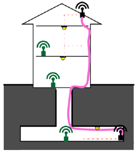
The radio access on the roof can be extended inside by means of a cable as shown in pink (e.g. coaxial cable, with support hardware) to provide radio access to an indoor station (on the lower right, underground.)
Another approach is to provide a gateway and a wireless extension topology, as shown in green. This could provide backhaul to a 3GPP access station in the lower right. Alternatively, all access within the building and underground could be accomplished by means of non-3GPP access. The (fixed mobile) 3GPP access remains on the roof, as a gateway providing network access.
The third approach is to make use of the existing power line deployment in the building and underground as a means of providing backhaul to the underground access point. There are a number of Power Line Communications (PLC) standards that are already used to provide data access to the edge of the electrical network, especially to physical locations that cannot be accessed easily in other ways.
Two prominent examples are Open PLC European Research Alliance (OPERA) [16] and G.9960 [17], which are used for support of Ethernet functionality over medium and low voltage power lines in a restricted range. In OPERA, information is modulated using OFDM with a set of 1536 sub-carriers. Effectively, this network provides an Ethernet over a power-line. G.9960 achieves PHY data rates up to 20 Mbit/s and highly robust communications with PHY bit rates up to 5 Mbit/s (using 4x repetition encoding.) 3GPP components can be integrated above this layer two standard that carries Ethernet frames.
OPERA achieves PHY data rates of up to 200 Mbit/s with a bandwidth of 30 MHz (this is typically not achieved in practice. Implementation is done in either 5 MHz or 10 MHz channels with much lower maximum PHY bit rate up to 40 Mbit/s and 80 Mbit/s respectively), for medium voltage (MV) cables. These throughput levels are not achievable at all in low voltage (LV) scenarios in which medium conditions are different to MV's. (This is an area of current development at the time this document was written, with researchers currently performing tests to evaluate the LV scenario.) The evolution of Ghn defined in ITU standard G.9960 might be more adequate for LV broadband power line (BPL) and for this use case (use of the LV cabling within a building) because it was specifically defined for domestic cables.
Whereas adding a cable for range extension through a structure or wireless extension topologies entail extra planning, materials and complexity, power lines already exist in all (modern) structures.
A.2 Pre-conditions p. 97
A facility will include components of the Smart Grid. The facility may either exist, or be planned and built from scratch.
The builders provide an efficient and effective means to extend wireless communication for Smart Grid communications underground (or in a portion of the facility which cannot be penetrated by emissions for wireless communications.)
Figure A.2-1 depicts an example deployment architecture.
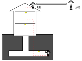
A PLC connection between the UE and the underground gNB has been configured. The UE has a preconfigured tunnel to the MNO's network. The UE's user plane tunnel transports both the user plane and control plane traffic of the underground gNB. The UEs that camp on the underground gNB have full 5G service, limited only by the (limited) bandwidth available (and added latency) due to the PLC and UE to gNB links.
A.3 Service Flows p. 97
The power lines in the facility are checked for their suitability for transmission of communications data. Power line communication termination is placed in the radio access station in the roof and the 3GPP access indoor station underground. Communications through the facility enable communication to be performed by the indoor station, then using the backhaul provided by the PLC, to communication via the access station on the roof.
A.4 Post-conditions p. 97
The facility has underground 3GPP communication without need for additional wires (for a coverage repeater) or an indoor wireless extension topology. While the performance of the underground access will be limited to the capabilities of the PLC performance, this suffices for the smart energy services operating in the underground location.
A.5 Existing features partly or fully covering the use case functionality p. 97
There are multiple ways that the configuration described in A.3 could be realized with existing 3GPP standards. For example, the indoor station could be a gNB whose backhaul is supported by means of PLC.
Another possibility would be for the indoor station to provide non-3GPP wireless access underground. The PLC could provide backhaul to the rooftop UE. The rooftop UE would then provide network access through a PLMN.
A.6 Potential New Requirements needed to support the use case p. 98
This use case is included for completeness but no new requirements have been identified.
$ Change history p. 99
![]()
![]()