Content for TS 22.261 Word version: 19.7.0
0…
4…
6…
6.4…
6.8…
6.12…
6.15…
6.16…
6.22…
6.26…
6.30…
6.37…
6.41…
6.43…
6.46…
7…
7.4…
7.9
7.10…
7.11…
8…
D…
D.3…
F…
G…
H
I
J…
D.3 Process automation
D.3.0 General
D.3.1 Remote control
D.3.2 Process and asset monitoring
D.3.3 Service area
D.4 Electric-power distribution and smart grid
D.4.0 General
D.4.1 Medium voltage
D.4.1.0 Overview
D.4.1.1 Service area and connection density
D.4.1.2 Security
D.4.2 High voltage
D.4.2.0 Overview
D.4.2.1 Service area and connection density
D.4.2.2 Security
D.5 Intelligent transport systems - infrastructure backhaul
D.5.0 General
D.5.1 Service area and connection density
...
...
D.3 Process automation p. 123
D.3.0 General |R18| p. 123
Process automation has much in common with factory automation (see clause D.2). Instead of discrete products (cars, chocolate bars, etc.), process automation addresses the production of bulk products such as petrol and reactive gases. In contrast to factory automation, motion control is of limited or no importance. Typical end-to-end latencies are 50 ms. User-experienced data rates, communication service availability, and connection density vary noticeably between applications. Below, we describe one emerging use case (remote control via mobile computational units, see clause D.3.1) and a contemporary use case (monitoring, see clause D.3.2).
Note that discrete automation fieldbuses (see clause D.2.0) are also used in process automation.
D.3.1 Remote control p. 123
Some of the interactions within a plant are conducted by automated control applications similar to those described in clause D.2. Here too, sensor output is requested in a cyclic fashion, and actuator commands are sent via the communication network between a controller and the actuator. Furthermore, there is an emerging need for the control of the plant by personnel on location. Typically, monitoring and managing of distributed control systems takes place in a dedicated control room.
Staff deployment to the plant itself occurs, for instance, during construction and commissioning of a plant and in the start-up phase of the processes. In this scenario, the locally deployed staff taps into the same real-time data as provided to the control room. These remote applications require high data rates (~ 100 Mbit/s) since the staff on location needs to view inaccessible locations with high definition (e.g. emergency valves) and since their colleagues in the control room benefit from high-definition footage from body cameras (HD or even 4K).
For both kinds of applications, a very high communication service availability is needed (99.999 9%). Typically, only a few control loops are fully automated and only handful of control personnel is deployed on location, so that the connection density is rather modest (~ 1,000 km²).
D.3.2 Process and asset monitoring p. 123
The monitoring of states, e.g. the level of the liquid of process reactors, is a paramount task in process automation. Due to the ever-changing states, measurement data is either pulled or pushed from the sensors in a cyclic manner. Some sensors are more conveniently accessed via wireless links, and monitoring of these sensors via handheld terminals, e.g. during maintenance, is also on the rise. This kind of application entails rather modest user experienced data rates (~ 1 Mbit/s), and since this kind of data is "only" an indicator for, e.g. what process should be stopped in order to avoid an overflow, and not for automated control loops, the requirement on communication service availability is comparably low (99.9%). Note that emergency valves and such are typically operated locally and do not rely on communication networks. However, many sensors are deployed in chemical plants etc., so that connection density can readily reach 10,000 km².
D.3.3 Service area p. 123
While, for instance, chemical plants and refineries readily can span over several square kilometres, the dedicated control rooms are typically only responsible for a subset of that area. Such subsets are often referred to as plants, and their typical size is 300 m x 300 m x 50 m.
D.4 Electric-power distribution and smart grid p. 124
D.4.0 General |R18| p. 124
In clause A.4 of TS 22.104 typical electric power distribution and smart grid use cases have been introduced. Here just give some examples.
D.4.1 Medium voltage p. 124
D.4.1.0 Overview |R18| p. 124
An energy-automation domain that now has standards based support by mobile-network technology is the backhaul electricity grid, i.e. the part of the distribution grid between primary substations (high voltage → medium voltage) and secondary substations (medium voltage → low voltage), and other smart grid services. In Figure D.4.1.0-1 we depict a medium-voltage ring together with energy-automation use cases that either are already deployed or are anticipated within the near future.
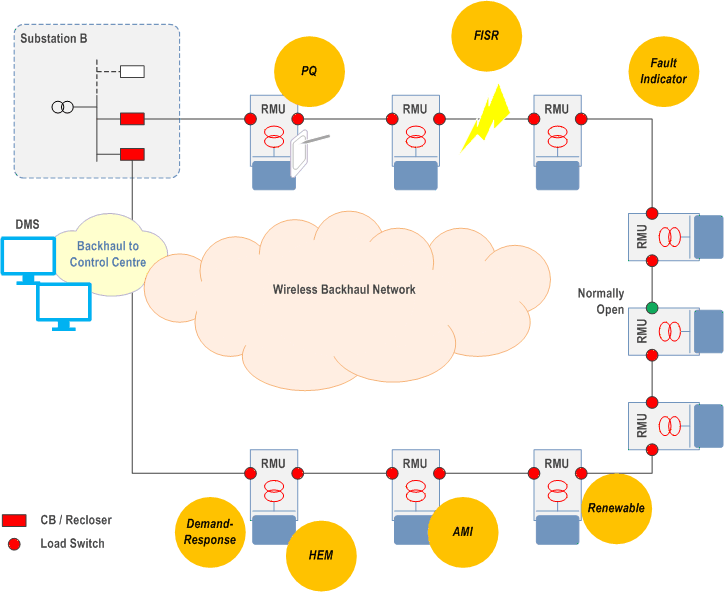
The primary substation and the secondary substations are supervised and controlled by a distribution-management system (DMS). If energy-automation devices in the medium-voltage power line ring need to communicate with each other and /or the DMS, a wireless backhaul network needs to be present (orange "cloud" in Figure D.4.1.0-1).
A majority of applications in electricity distribution adhere to the communication standard IEC 60870-5-104. However, its modern "cousin" IEC 61850 experiences rapidly increasing popularity. The communication requirements for IEC 61850 applications can be found in EC 61850-90-4. Communication in wide-area networks is described in IEC 61850-90-12.
Usually, power line ring structures have to be open in order to avoid a power-imbalance in the ring (green dot in the Figure). Examples for energy-automation that already is implemented in medium-voltage grids (albeit in low numbers) are power-quality measurements and the measurement of secondary-substation parameters (temperature, power load, etc.) [13]. Other use cases are demand response and the control of distributed, renewable energy resources (e.g. photovoltaics).
A use case that could also be realised in the future is fault isolation and system restoration (FISR). FISR automates the management of faults in the distribution grid. It supports the localization of the fault, the isolation of the fault, and the restoration of the power delivery. For this kind of automation, the pertinent sensors and actuators broadcast telegrams about their states (e.g., "emergency closer idle") and about actions (e.g., "activating closer") into the backhaul network. This information is used by the ring main units (RMUs) as input for their decision algorithms. We illustrate this use of automation telegrams for an automated FISR event in Figure D.4.1.0-1. Let us assume the distribution lines are cut at the location indicated by the bolt of lightning in the Figure. In that case, the RMUs between the bolt and the green load switch (open) will be without power. The RMUs next to the "bolt" automatically open their load switches after having sensed the loss of electric connectivity between them. They both broadcast these actions into the backhaul network. Typically, these telegrams are repeated many times while the time between adjacent telegrams increases exponentially. This communication patterns leads to sudden, distributed surges in the consumed communication bandwidth. After the RMUs next to the "bolt" have opened their switch, the RMU that so far has kept the power line ring open (green dot in Figure D.4.1.0-1) closes the load switch. This event too is broadcasted into the backhaul network. The typical maximum end-to-end latency for this kind of broadcast is 25 ms with a peak experienced data rate of 10 Mbit/s. Note that the distribution system typically subscribes to telegrams from all RMUs in order to keep abreast with the happenings in the distribution grid.
Automatic fault handling in the distribution grid shortens outage time and offloads the operators in the distribution control centre for more complicated situations. Therefore, automated FISR can help to improve performance indexes like System Average Interruption Duration Index and System Average Interruption Frequency Index.
Automation telegrams are typically distributed via domain multicast. As explained above, the related communication pattern can be "bursty", i.e. only few automation telegrams are sent when the distribution network operates nominally (~ 1 kbit/s), but, for instance, a disruption in the power line triggers a short-lived avalanche of telegrams from related applications in the ring (≥ 1 Mbit/s).
D.4.1.1 Service area and connection density p. 125
Service coverage is only required along the medium-voltage line. In Europe, the line often forms a loop (see Figure D.4.1.0-1), while deployments in other countries, e.g. the USA, tend to extend linearly over distances up to ~ 100 km. The vertical dimension of the poles in a medium voltages line is typically less than 40 m. Especially in urban areas, the number of ring main units can be rather large (> 10 km-2), and the number of connections to each ring main unit is expected to increase swiftly once economical, suitable wireless connectivity becomes available. We predict connection densities of up to 1.000 km-2.
D.4.1.2 Security p. 125
Due to its central role in virtually every country on earth, electricity distribution is heavily regulated. Security assessments for, e.g. deployments in North America, need to adhere to the NERC CIP suite [14]. Technical implementations are described in standard suites such as IEC 62351.
D.4.2 High voltage p. 125
D.4.2.0 Overview |R18| p. 125
In order to avoid region- or even nation-wide power outages, wide-area power system protection is on the rise. "When a major power system disturbance occurs, protection and control actions are required to stop the power system degradation, restore the system to a normal state, and minimize the impact of the disturbance. The present control actions are not designed for a fast-developing disturbance and can be too slow. Local protection systems are not able to consider the overall system, which can be affected by the disturbance. Wide area disturbance protection is a concept of using system-wide information and sending selected local information to a remote location to counteract propagation of the major disturbances in the power system." [15]. Protection actions include, "among others, changes in demand (e.g. load shedding), changes in generation or system configuration to maintain system stability or integrity and specific actions to maintain or restore acceptable voltage levels." [16]. One specific application is phasor measurement for the stabilisation of the alternating-current phase in a transport network. For this, the voltage phase is measured locally and sent to a remote-control centre. There, this information is processed, and automated actions are triggered. One action can be the submission of telegrams to power plants, instructing them to either accelerate or deaccelerate their power generators in order to keep the voltage phase in the transport network stable. A comprehensive overview of this topic can be found elsewhere in the literature [17].
This kind of automation requires very low end-to-end latencies (5 ms) [16] and-due to its critical importance for the operation of society-a very high communication service availability (99.999 9%).
D.4.2.1 Service area and connection density p. 126
As is the case for medium-voltage distribution networks (see Annex D.4.1), connectivity in high-voltage automation has to be provided mainly along the power line. The distances to be covered can be substantial (hundreds of kilometres in rural settings), while shorter links are prevalent in metropolitan areas. The number of connections in wide-area power system protection is rather low; but-due to the sliver-shaped service area-the connection density can be rather high (1,000 km²).
D.4.2.2 Security p. 126
Due to its central role in virtually every country on earth, electricity distribution is heavily regulated. Security assessments for, e.g. deployments in North America, need to adhere to the NERC CIP suite [14]. Technical implementations are described in standard suites such as IEC 62351.
D.5 Intelligent transport systems - infrastructure backhaul p. 126
D.5.0 General |R18| p. 126
Intelligent Transport Systems (ITS) embrace a wide variety of communications-related applications that are intended to increase travel safety, minimize environmental impact, improve traffic management, and maximize the benefits of transportation to both commercial users and the general public. Over recent years, the emphasis in intelligent vehicle research has turned to co-operative systems, in which the traffic participants (vehicles, bicycles, pedestrians, etc.) communicate with each other and/or with the infrastructure.
Cooperative ITS is the term used to describe technology that allows vehicles to become connected to each other, and to the infrastructure and other parts of the transport network. In addition to what drivers can immediately see around them, and what vehicle sensors can detect, all parts of the transport system will increasingly be able to share information to improve decision making. Thus, this technology can improve road safety through avoiding collisions, but also assist in reducing congestion and improving traffic flows, and reduce environmental impacts. Once the basic technology is in place as a platform, an array of applications can be developed.
Cooperative ITS can greatly increase the quality and reliability of information available about vehicles, their location and the road environment. In the future, cars will know the location of road works and the switching phases of traffic lights ahead, and they will be able to react accordingly. This will make for safer and more convenient travel and faster arrival at the destination. On-board driver assistance, coupled with two-way communication between vehicles and between vehicles and road infrastructure, can help drivers to better control their vehicle and hence have positive effects in terms of safety and traffic efficiency. An important role in this plays the so-called road side units (RSUs). Vehicles can also function as sensors reporting weather and road conditions including incidents. In this way, cars can be used as information sources for high-quality information services.
RSUs are connected to the traffic control centre for management and control purposes. They broadcast, e.g., traffic light information (RSU → vehicle) and traffic information from the traffic-control centre (TCC) via the RSU to the vehicles (TCC → RSU → vehicle). RSUs also collect vehicle probe data for the traffic control centre (vehicle → RSU → TCC). For reliable distribution of data, low-latency and high-capacity connections between RSUs (e.g. traffic lights, traffic signs, etc.) and the TCC are required. This type of application comes with rather tight end-to-end latency requirements for the communication service between RSU and TCC (10 ms), since relayed data needs to be processed in the TCC and, if needed, the results are forwarded to neighbouring RSUs. Also, the availability of the communication service has to be very high (99.999 9 %) in order to compete with existing wired technology and in order to justify the costly deployment and maintenance of RSUs. Furthermore, due to considerably large aggregation areas (see clause D.5.1), considerable amounts of data need to be backhauled to the TCC (up to 10 Mbit/s per RSU).
D.5.1 Service area and connection density p. 127
It is relatively hard to provide estimates for the service area dimension. One reason is that it depends on the placement of the base station relative to the RSUs. Also, the RSUs can, in principle, act as relay nodes for each other. The service area dimension stated in Table 7.2.3.2-1 indicates the size of the typical data collection area of an RSU (2 km along a road), from which the minimum spacing of RSUs can be inferred. The connection density can be quite high in case data is relayed between RSUs, i.e. along the road (1,000 km²).
E Void
![]()
![]()
![]()