Content for TS 38.305 Word version: 18.3.0
1…
4…
5…
6…
6.5…
6.7…
7…
7.3A…
7.4…
7.6…
7.11…
7.12…
8…
8.1.2.1a…
8.1.3…
8.2…
8.3…
8.4…
8.5…
8.6…
8.7…
8.8…
8.9…
8.10…
8.11…
8.12…
8.13…
8.14…
8.15…
A…
6 Signalling protocols and interfaces
6.1 Network interfaces supporting positioning operations
6.1.1 General LCS control plane architecture
6.1.2 NR-Uu interface
6.1.3 LTE-Uu interface
6.1.4 NG-C interface
6.1.5 NL1 interface
6.1.6 F1 interface
6.1.7 NR PC5 interface
6.2 UE-terminated protocols
6.2.1 LTE Positioning Protocol (LPP)
6.2.2 Radio Resource Control (RRC) for NR
6.2.3 Radio Resource Control (RRC) for LTE
6.2.4 Medium Access Control (MAC) for NR
6.2.5 Sidelink Positioning Protocol (SLPP)
6.3 NG-RAN Node terminated protocols
6.3.1 NR Positioning Protocol A (NRPPa)
6.3.2 NG Application Protocol (NGAP)
6.4 Signalling between an LMF and UE
6.4.1 Protocol Layering
6.4.2 LPP PDU Transfer
6.4.3 SLPP PDU Transfer
...
...
6 Signalling protocols and interfaces p. 31
6.1 Network interfaces supporting positioning operations p. 31
6.1.1 General LCS control plane architecture p. 31
The general LCS control plane architecture in the 5GS applicable to a target UE with NG-RAN access is defined in TS 23.501 and TS 23.273. The general architecture to support ranging based services and sidelink positioning in the 5GS is provided in TS 23.586.
6.1.2 NR-Uu interface p. 31
The NR-Uu interface, connecting the UE to the gNB over the air, is used as one of several transport links for the NR positioning protocol(s) for a target UE with NR access to NG-RAN.
6.1.3 LTE-Uu interface p. 31
The LTE-Uu interface, connecting the UE to the ng-eNB over the air, is used as one of several transport links for the LTE positioning protocol(s) for a target UE with LTE access to NG-RAN.
6.1.4 NG-C interface p. 31
The NG-C interface between the gNB and the AMF and between the ng-eNB and the AMF is transparent to all UE-positioning-related procedures. It is involved in these procedures only as a transport link for the NR positioning protocol(s).
For gNB related positioning procedures, the NG-C interface transparently transports both positioning requests from the LMF to the gNB and positioning results from the gNB to the LMF.
For ng-eNB related positioning procedures, the NG-C interface transparently transports both positioning requests from the LMF to the ng-eNB and positioning results from the ng-eNB to the LMF.
For delivery of broadcast assistance data information, the NG-C interface transparently transports both the assistance data information from the LMF to the NG-RAN node for broadcasting and the feedback information on assistance information broadcasting from the NG-RAN node to the LMF. The NG-C interface is also used by an AMF to transparently transport ciphering keys via NG-RAN node to UEs using a NAS message. The ciphering keys are used to decipher broadcast assistance data information, if the broadcast assistance data information is ciphered.
6.1.5 NL1 interface p. 31
The NL1 interface, between the LMF and the AMF, is transparent to all UE related, gNB related and ng-eNB related positioning procedures. It is used only as a transport link for the LTE Positioning Protocols LPP, SLPP and NR Positioning Protocol A NRPPa.
6.1.6 F1 interface |R16| p. 32
In case of split gNB architecture, the F1 interface is used to support the exchange of positioning information between the gNB-DU and the gNB-CU; it is also used transparently as a transport link for the LPP and SLPP.
6.1.7 NR PC5 interface |R18| p. 32
The NR PC5 interface is used as transport link for the SL positioning protocol SLPP.
6.2 UE-terminated protocols p. 32
6.2.1 LTE Positioning Protocol (LPP) p. 32
The LTE Positioning Protocol (LPP) is terminated between a target device (the UE in the control-plane case or SET in the user-plane case) and a positioning server (the LMF in the control-plane case or SLP in the user-plane case). It may use either the control- or user-plane protocols as underlying transport. In this specification, only control plane use of LPP is defined. User plane support of LPP is defined in [15] and [16].
LPP is also used point-to-point between a location server and a PRU. The LPP procedures and messages specified for a target device equally apply to a PRU, as specified in TS 23.273.
LPP messages are carried as transparent PDUs across intermediate network interfaces using the appropriate protocols (e.g., NGAP over the NG-C interface, NAS/RRC over the LTE-Uu and NR-Uu interfaces). The LPP protocol is intended to enable positioning for NR and LTE using a multiplicity of different position methods, while isolating the details of any particular positioning method and the specifics of the underlying transport from one another.
The protocol operates on a transaction basis between a target device and a server, with each transaction taking place as an independent procedure. More than one such procedure may be in progress at any given moment. An LPP procedure may involve a request/response pairing of messages or one or more "unsolicited" messages. Each procedure has a single objective (e.g., transfer of assistance data, exchange of LPP related capabilities, or positioning of a target device according to some QoS and use of one or more positioning methods). Multiple procedures, in series and/or in parallel, can be used to achieve more complex objectives (e.g., positioning of a target device in association with transfer of assistance data and exchange of LPP related capabilities). Multiple procedures also enable more than one positioning attempt to be ongoing at the same time (e.g., to obtain a coarse location estimate with low delay while a more accurate location estimate is being obtained with higher delay).
An LPP session is defined between a positioning server and the target device, the details of its relation with transactions are described in clause 4.1.2 of TS 37.355.
For the 3GPP 5GS Control Plane solution defined in TS 23.501, TS 23.502 and TS 23.273, the UE is the target device and the LMF is the server. For SUPL 2.0 support, the SUPL Enabled Terminal (SET) is the target device and the SUPL Location Platform (SLP) is the server. The operations controlled through LPP are described further in clause 7.1.
LPP defined data structures for assistance data information are reused for supporting RRC broadcast of assistance data information which are embedded in positioning SIBs. This enables broadcast assistance data using the same data structures which are used for point to point location.
6.2.2 Radio Resource Control (RRC) for NR p. 32
The RRC protocol for NR is terminated between the gNB and the UE. It provides transport for LPP and SLPP messages over the NR-Uu interface.
In addition to providing transport for LPP and SLPP messages over the NR-Uu interface, it supports transfer of measurements that may be used for positioning purposes through the existing measurement systems specified in TS 38.331.
The RRC protocol for NR also supports broadcasting of assistance data via positioning System Information messages.
The RRC protocol for NR is also used to configure UEs with a sounding reference signal (SRS) for SRS transmission in RRC_CONNECTED and RRC_INACTIVE to support NG-RAN measurements for NR positioning, provide pre-configured measurement gap configuration(s) and pre-configured PRS processing window for DL-PRS measurement and report the UE TxTEG (Tx Timing Error Group) for UL-TDOA.
The RRC protocol for NR also supports SL-PRS Resource Allocation via system information or dedicated signalling or pre-configuration.
6.2.3 Radio Resource Control (RRC) for LTE p. 33
The RRC protocol for LTE is terminated between the ng-eNB and the UE. In addition to providing transport for LPP messages over the LTE-Uu interface, it supports transfer of measurements that may be used for positioning purposes through the existing measurement systems specified in TS 36.331.
The RRC protocol for LTE also supports broadcasting of assistance data via positioning System Information messages.
6.2.4 Medium Access Control (MAC) for NR |R16| p. 33
The MAC protocol for NR supports activation and deactivation of configured semi-persistent SRS resource sets as specified in TS 38.321 to support NG-RAN measurements for NR positioning.
The MAC protocol for NR also supports request of positioning measurement gap activation and deactivation from a UE, and activation and deactivation of pre-configured measurement gap from the NG-RAN as specified in TS 38.321.
The MAC protocol for NR can also be used to activate and deactivate of PRS Processing Window as specified in TS 38.321.
The MAC protocol for NR also supports services and functions for SL-PRS transmission and reception as specified in TS 38.321.
6.2.5 Sidelink Positioning Protocol (SLPP) |R18| p. 33
The Sidelink Positioning Protocol (SLPP) is exchanged over PC5-U reference point between UEs (e.g., target UE, anchor UE, server UE) to manage the ranging/sidelink positioning sessions among a group of UEs.
SLPP is also exchanged between a target UE and a LMF to support sidelink positioning. In this case, the SLPP messages are carried as transparent PDUs across intermediate network interfaces using the appropriate protocols (e.g., NGAP over the NG-C interface, NAS/RRC over the NR-Uu interface).
The SLPP protocol is intended to enable sidelink positioning and ranging using a multiplicity of different position methods, while isolating the details of any particular positioning method and the specifics of the underlying transport from one another.
The protocol operates on a transaction basis between UEs and between a UE and an LMF, with each transaction taking place as an independent procedure as described in TS 38.355. More than one such procedure may be in progress at any given moment. A SLPP procedure may involve a request/response pairing of messages or one or more "unsolicited" messages. Each procedure has a single objective (e.g., transfer of assistance data, exchange of SLPP related capabilities, or positioning/ranging of a target device according to some QoS and use of one or more SL positioning methods). Multiple procedures, in series and/or in parallel, can be used to achieve more complex objectives (e.g., positioning of a target device in association with transfer of assistance data and exchange of SLPP related capabilities).
An SLPP Session is used between UEs or between a UE and an LMF to fulfil a ranging/sidelink positioning service request. A SLPP Session comprises one or more SLPP transactions. A UE may simultaneously participate in multiple SLPP sessions. For UE-only scenarios, a SLPP Session ID is used to identify all SLPP transactions belonging to an SLPP session which enables UEs to uniquely distinguish SLPP messages for one session from SLPP messages for other sessions.
6.3 NG-RAN Node terminated protocols p. 34
6.3.1 NR Positioning Protocol A (NRPPa) p. 34
The NR Positioning Protocol A (NRPPa) carries information between the NG-RAN Node and the LMF. It is used to support the following positioning functions:
- E-CID for E-UTRA where measurements are transferred from the ng-eNB to the LMF.
- Data collection from ng-eNB's and gNB's for support of OTDOA positioning for E-UTRA.
- Cell-ID and Cell Portion ID retrieval from gNB's for support of NR Cell ID positioning method.
- Exchange of information between LMF and NG-RAN node for the purpose of assistance data broadcasting.
- NR E-CID where measurements are transferred from the gNB to the LMF.
- NR Multi-RTT where measurements are transferred from the gNB to the LMF.
- NR UL-AoA where measurements are transferred from the gNB to the LMF.
- NR UL-TDOA where measurements are transferred from the gNB to the LMF.
- Data collection from gNBs for support of DL-TDOA, DL-AoD, Multi-RTT, UL-TDOA, UL-AoA.
- Measurement Preconfiguration Information Transfer which allows the LMF to request the NG-RAN node to pre-configure and activate/deactivate measurement gap and/or PRS processing window.
- Area-specific SRS Information Transfer which allows the LMF to notify the NG-RAN node about area-specific SRS configuration information.
6.3.2 NG Application Protocol (NGAP) p. 34
The NGAP protocol, terminated between the AMF and the NG-RAN Node, is used as transport for LPP and NRPPa messages over the NG-C interface. The NGAP protocol is also used to instigate and terminate NG-RAN Node related positioning procedures.
6.4 Signalling between an LMF and UE p. 34
6.4.1 Protocol Layering p. 34
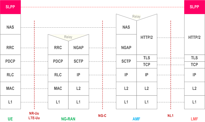
Figure 6.4.1-1 shows the protocol layering used to support transfer of LPP messages between an LMF and UE. The LPP PDU is carried in NAS PDU between the AMF and the UE.

Figure 6.4.1-2 shows the protocol layering used to support transfer of SLPP messages between an LMF and UE. The SLPP PDU is carried in NAS PDU between the AMF and the UE.
6.4.2 LPP PDU Transfer p. 35
Figure 6.4.2-1 shows the transfer of an LPP PDU between an LMF and UE, in the network- and UE-triggered cases. These two cases may occur separately or as parts of a single more complex operation.
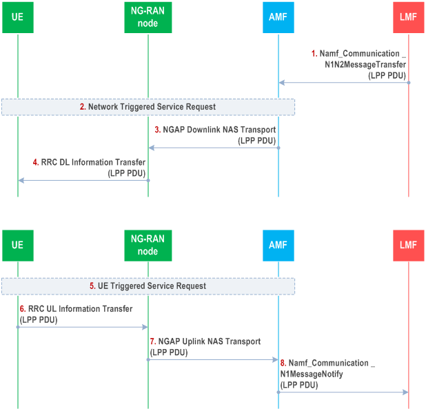
Step 1.
Steps 1 to 4 may occur before, after, or at the same time as steps 5 to 8. Steps 1 to 4 and steps 5 to 8 may also be repeated. Steps 1 to 4 are triggered when the LMF needs to send an LPP message to the UE as part of some LPP positioning activity. The LMF then invokes the Namf_Communication _N1N2MessageTransfer service operation towards the AMF to request the transfer of a LPP PDU to the UE. The service operation includes the LPP PDU together with the LCS Correlation ID in the N1 Message Container as defined in TS 29.518.
Step 2.
If the UE is in CM-IDLE state (e.g. if the NG connection was previously released due to data and signalling inactivity), the AMF initiates a network triggered service request as defined in TS 23.502 in order to establish a signalling connection with the UE and assign a serving NG-RAN node.
Step 3.
The AMF includes the LPP PDU in the payload container of a DL NAS Transport message, and a Routing Identifier identifying the LMF in the Additional Information of the DL NAS Transport message defined in TS 24.501. The AMF then sends the DL NAS Transport message to the serving NG-RAN Node in an NGAP Downlink NAS Transport message defined in TS 38.413. The AMF need not retain state information for this transfer; it can treat any response in step 7 as a separate non-associated transfer.
Step 4.
The NG-RAN Node forwards the DL NAS Transport message to the UE in an RRC DL Information Transfer message.
Step 5.
Steps 5 to 8 are triggered when the UE needs to send an LPP PDU to the LMF as part of some LPP positioning activity. If the UE is in CM-IDLE state, the UE instigates a UE triggered service request as defined in TS 23.502 in order to establish a signalling connection with the AMF and assign a serving NG-RAN node.
Step 6.
The UE includes the LPP PDU in the payload container of an UL NAS Transport message, and the Routing Identifier, which has been received in step 4, in the Additional Information of the UL NAS Transport message defined in TS 24.501. The UE then sends the UL NAS Transport message to the serving NG-RAN node in an RRC UL Information Transfer message.
Step 7.
The NG-RAN node forwards the UL NAS Transport Message to the AMF in an NGAP Uplink NAS Transport message.
Step 8.
The AMF invokes the Namf_Communication_N1MessageNotify service operation towards the LMF indicated by the Routing Identifier received in step 7. The service operation includes the LPP PDU received in step 7 together with the LCS Correlation ID in the N1 Message Container as defined in TS 29.518.
6.4.3 SLPP PDU Transfer |R18| p. 37
Figure 6.4.3-1 shows the transfer of an SLPP PDU between an LMF and UE, in the network- and UE-triggered cases. These two cases may occur separately or as parts of a single more complex operation.
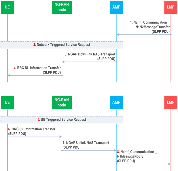
Step 1.
Steps 1 to 4 may occur before, after, or at the same time as steps 5 to 8. Steps 1 to 4 and steps 5 to 8 may also be repeated. Steps 1 to 4 are triggered when the LMF needs to send an SLPP message to the UE as part of some SLPP positioning activity. The LMF then invokes the Namf_Communication _N1N2MessageTransfer service operation towards the AMF to request the transfer of a SLPP PDU to the UE. The service operation includes the SLPP PDU together with the LCS Correlation ID in the N1 Message Container as defined in TS 29.518.
Step 2.
If the UE is in CM-IDLE state (e.g. if the NG connection was previously released due to data and signalling inactivity), the AMF initiates a network triggered service request as defined in TS 23.502 in order to establish a signalling connection with the UE and assign a serving NG-RAN node.
Step 3.
The AMF includes the SLPP PDU in the payload container of a DL NAS Transport message, and a Routing Identifier identifying the LMF in the Additional Information of the DL NAS Transport message defined in TS 24.501. The AMF then sends the DL NAS Transport message to the serving NG-RAN Node in an NGAP Downlink NAS Transport message defined in TS 38.413. The AMF need not retain state information for this transfer; it can treat any response in step 7 as a separate non-associated transfer.
Step 4.
The NG-RAN Node forwards the DL NAS Transport message to the UE in an RRC DL Information Transfer message.
Step 5.
Steps 5 to 8 are triggered when the UE needs to send an SLPP PDU to the LMF as part of some SLPP positioning activity. If the UE is in CM-IDLE state, the UE instigates a UE triggered service request as defined in TS 23.502 in order to establish a signalling connection with the AMF and assign a serving NG-RAN node.
Step 6.
The UE includes the SLPP PDU in the payload container of an UL NAS Transport message, and the Routing Identifier, which has been received in step 4, in the Additional Information of the UL NAS Transport message defined in TS 24.501. The UE then sends the UL NAS Transport message to the serving NG-RAN node in an RRC UL Information Transfer message.
Step 7.
The NG-RAN node forwards the UL NAS Transport Message to the AMF in an NGAP Uplink NAS Transport message.
Step 8.
The AMF invokes the Namf_Communication_N1MessageNotify service operation towards the LMF indicated by the Routing Identifier received in step 7. The service operation includes the SLPP PDU received in step 7 together with the LCS Correlation ID in the N1 Message Container as defined in TS 29.518.
![]()
![]()
![]()