Content for TS 38.305 Word version: 18.1.0
1…
4…
5…
6…
6.5…
6.7…
7…
7.3A…
7.4…
7.6…
7.11…
7.12…
8…
8.1.2.1a…
8.1.3…
8.2…
8.3…
8.4…
8.5…
8.6…
8.7…
8.8…
8.9…
8.10…
8.11…
8.12…
8.13…
8.14…
8.15…
A…
8 Positioning methods and Supporting Procedures
8.1 GNSS positioning methods
8.1.1 General
8.1.2 Information to be transferred between NG-RAN/5GC Elements
8.1.2.0 General
8.1.2.1 Information that may be transferred from the LMF to UE
8.1.2.1.0 General
8.1.2.1.1 Reference Time
8.1.2.1.2 Reference Location
8.1.2.1.3 Ionospheric Models
8.1.2.1.4 Earth Orientation Parameters
8.1.2.1.5 GNSS-GNSS Time Offsets
8.1.2.1.6 Differential GNSS Corrections
8.1.2.1.7 Ephemeris and Clock Models
8.1.2.1.8 Real-Time Integrity
8.1.2.1.9 Data Bit Assistance
8.1.2.1.10 Acquisition Assistance
8.1.2.1.11 Almanac
8.1.2.1.12 UTC Models
8.1.2.1.13 RTK Reference Station Information
8.1.2.1.14 RTK Auxiliary Station Data
8.1.2.1.15 RTK Observations
8.1.2.1.16 RTK Common Observation Information
8.1.2.1.17 GLONASS RTK Bias Information
8.1.2.1.18 RTK MAC Correction Differences
8.1.2.1.19 RTK Residuals
8.1.2.1.20 RTK FKP Gradients
8.1.2.1.21 SSR Orbit Corrections
8.1.2.1.22 SSR Clock Corrections
8.1.2.1.23 SSR Code Bias
8.1.2.1.24 SSR Phase Bias
8.1.2.1.25 SSR STEC Corrections
8.1.2.1.26 SSR Gridded Correction
8.1.2.1.27 SSR URA
8.1.2.1.28 SSR Correction Points
8.1.2.1.29 Integrity Service Parameters
8.1.2.1.30 Integrity Alerts
8.1.2.1.31 SSR IOD Update
8.1.2.1.32 SSR Satellite PCV Residuals
...
...
8 Positioning methods and Supporting Procedures p. 76
8.1 GNSS positioning methods p. 76
8.1.1 General p. 76
A navigation satellite system provides autonomous geo-spatial positioning with either global or regional coverage. Augmentation systems, such as SBAS, are navigation satellite systems that provide regional coverage to augment the navigation systems with global coverage.
By definition, GNSS refers to satellite constellations that achieve global coverage, however, in 3GPP specifications the term GNSS is used to encompass global, regional, and augmentation satellite systems. The following GNSSs are supported in this version of the specification:
- GPS and its modernization [5], [6], [7]; (global coverage)
- Galileo [8]; (global coverage)
- GLONASS [9]; (global coverage)
- Satellite Based Augmentation Systems (SBAS), including WAAS, EGNOS, MSAS, and GAGAN [11]; (regional coverage)
- Quasi-Zenith Satellite System (QZSS) [10]; (regional coverage)
- BeiDou Navigation Satellite System (BDS) [20] [34] [44] [45]. (global coverage)
- NAVigation with Indian Constellation (NavIC) [43]. (regional coverage)
- extra satellites can improve availability (of satellites at a particular location) and results in an improved ability to work in areas where satellite signals can be obscured, such as in urban canyons;
- extra satellites and signals can improve reliability, i.e., with extra measurements the data redundancy is increased, which helps identify any measurement outlier problems;
- extra satellites and signals can improve accuracy due to improved measurement geometry and improved ranging signals from modernized satellites.
- reduce the UE GNSS start-up and acquisition times; the search window can be limited and the measurements speed up significantly;
- increase the UE GNSS sensitivity; positioning assistance messages are obtained via NG-RAN so the UE GNSS receiver can operate also in low SNR situations when it is unable to demodulate GNSS satellite signals;
- allow the UE to consume less handset power than with stand-alone GNSS; this is due to rapid start-up times as the GNSS receiver can be in idle mode when it is not needed;
- allow the UE to compute its position with a better accuracy; RTK corrections (for N-RTK) and GNSS physical models (for SSR/PPP) are obtained via NG-RAN so the UE can use these assistance data, together with its own measurements, i.e., code and carrier phase measurements, to enable computation of a position with a high accuracy;
- allow the UE to determine and report the integrity results of the calculated location; the UE can use the integrity requirements and assistance data obtained via NG-RAN, together with its own measurements, to determine the integrity results of the calculated location.
- UE-Assisted: The UE performs GNSS measurements (pseudo-ranges, pseudo Doppler, carrier phase ranges, etc.) and sends these measurements to the LMF where the position calculation takes place, possibly using additional measurements from other (non GNSS) sources;
- UE-Based: The UE performs GNSS measurements and calculates its own location, possibly using additional measurements from other (non GNSS) sources and assistance data from the LMF.
- data assisting the measurements: e.g. reference time, visible satellite list, satellite signal Doppler, code phase, Doppler and code phase search windows;
- data providing means for position calculation: e.g. reference time, reference position, satellite ephemeris, clock corrections, code and carrier phase measurements from a GNSS reference receiver or network of receivers;
- data increasing the position accuracy: e.g. satellite code biases, satellite orbit corrections, satellite clock corrections, atmospheric models, RTK residuals, gradients;
- data facilitating the integrity results determination of the calculated location.
8.1.2 Information to be transferred between NG-RAN/5GC Elements p. 77
8.1.2.0 General |R18| p. 77
This clause defines the information that may be transferred between LMF and UE.
8.1.2.1 Information that may be transferred from the LMF to UE p. 77
8.1.2.1.0 General |R18| p. 77
Table 8.1.2.1.0-1 lists assistance data for both UE-assisted and UE-based modes that may be sent from the LMF to the UE.
| Assistance Data |
|---|
| Reference Time |
| Reference Location |
| Ionospheric Models |
| Earth Orientation Parameters |
| GNSS-GNSS Time Offsets |
| Differential GNSS Corrections |
| Ephemeris and Clock Models |
| Real-Time Integrity |
| Data Bit Assistance |
| Acquisition Assistance |
| Almanac |
| UTC Models |
| RTK Reference Station Information |
| RTK Auxiliary Station Data |
| RTK Observations |
| RTK Common Observation Information |
| GLONASS RTK Bias Information |
| RTK MAC Correction Differences |
| RTK Residuals |
| RTK FKP Gradients |
| SSR Orbit Corrections |
| SSR Clock Corrections |
| SSR Code Bias |
| SSR Phase Bias |
| SSR STEC Corrections |
| SSR Gridded Correction |
| SSR URA |
| SSR Correction Points |
| Integrity Service Parameters |
| Integrity Alerts |
| SSR IOD Update |
| SSR Satellite PCV Residuals |
8.1.2.1.1 Reference Time p. 78
Reference Time assistance provides the GNSS receiver with coarse or fine GNSS time information. The specific GNSS system times (e.g., GPS, Galileo, GLONASS, BDS, NavIC system time) shall be indicated with a GNSS ID.
In case of coarse time assistance only, the Reference Time provides an estimate of the current GNSS system time (where the specific GNSS is indicated by a GNSS ID). The LMF should achieve an accuracy of ±3 seconds for this time including allowing for the transmission delay between LMF and UE.
In case of fine time assistance, the Reference Time provides the relation between GNSS system time (where the specific GNSS is indicated by a GNSS ID) and NG-RAN air-interface timing.
8.1.2.1.2 Reference Location p. 78
Reference Location assistance provides the GNSS receiver with an a priori estimate of its location (e.g., obtained via Cell-ID, OTDOA positioning, etc.) together with its uncertainty.
The geodetic reference frame shall be WGS-84, as specified in TS 23.032.
8.1.2.1.3 Ionospheric Models p. 78
Ionospheric Model assistance provides the GNSS receiver with parameters to model the propagation delay of the GNSS signals through the ionosphere. Ionospheric Model parameters as specified by GPS [5], Galileo [8], QZSS [10], BDS [20] [34] [44] [45], and NavIC [43] may be provided.
8.1.2.1.4 Earth Orientation Parameters p. 79
Earth Orientation Parameters (EOP) assistance provides the GNSS receiver with parameters needed to construct the ECEF-to-ECI coordinate transformation as specified by GPS [5].
8.1.2.1.5 GNSS-GNSS Time Offsets p. 79
GNSS-GNSS Time Offsets assistance provides the GNSS receiver with parameters to correlate GNSS time (where the specific GNSS is indicated by a GNSS-1 ID) of one GNSS with other GNSS time (where the specific GNSS is indicated by a GNSS-2 ID). GNSS-GNSS Time Offsets parameters as specified by GPS [5], Galileo [8], GLONASS [9], QZSS [10], BDS [20] [34] [44] [45], and NavIC [43] may be provided.
8.1.2.1.6 Differential GNSS Corrections p. 79
Differential GNSS Corrections assistance provides the GNSS receiver with pseudo-range and pseudo-range-rate corrections to reduce biases in GNSS receiver measurements as specified in [12]. The specific GNSS for which the corrections are valid is indicated by a GNSS-ID.
8.1.2.1.7 Ephemeris and Clock Models p. 79
Ephemeris and Clock Models assistance provides the GNSS receiver with parameters to calculate the GNSS satellite position and clock offsets. The various GNSSs use different model parameters and formats, and all parameter formats as defined by the individual GNSSs are supported by the signalling.
8.1.2.1.8 Real-Time Integrity p. 79
Real-Time Integrity assistance provides the GNSS receiver with information about the health status of a GNSS constellation (where the specific GNSS is indicated by a GNSS ID).
For integrity purposes (as per Clause 8.1.1a), a GNSS satellite and signal combination should be considered as being marked "Do Not Use" (DNU) if the satellite ID and signal are present in the list of unhealthy (bad) signals.
8.1.2.1.9 Data Bit Assistance p. 79
Data Bit Assistance provides the GNSS receiver with information about data bits or symbols transmitted by a GNSS satellite at a certain time (where the specific GNSS is indicated by a GNSS ID). This information may be used by the UE for sensitivity assistance (data wipe-off) and time recovery.
8.1.2.1.10 Acquisition Assistance p. 79
Acquisition Assistance provides the GNSS receiver with information about visible satellites, reference time, expected code-phase, expected Doppler, search windows (i.e., code and Doppler uncertainty) and other information of the GNSS signals (where the specific GNSS is indicated by a GNSS ID) to enable a fast acquisition of the GNSS signals.
8.1.2.1.11 Almanac p. 79
Almanac assistance provides the GNSS receiver with parameters to calculate the coarse (long-term) GNSS satellite position and clock offsets. The various GNSSs use different model parameters and formats, and all parameter formats as defined by the individual GNSSs are supported by the signalling.
8.1.2.1.12 UTC Models p. 79
UTC Models assistance provides the GNSS receiver with parameters needed to relate GNSS system time (where the specific GNSS is indicated by a GNSS ID) to Universal Coordinated Time. The various GNSSs use different model parameters and formats, and all parameter formats as defined by the individual GNSSs are supported by the signalling.
8.1.2.1.13 RTK Reference Station Information p. 80
RTK Reference Station Information provides the GNSS receiver with the Earth-Centered, Earth-Fixed (ECEF) coordinates of the Reference Station's installed antenna's ARP, and the height of the ARP above the survey monument. Additionally, this assistance data provides information about the antenna type installed at the reference site.
8.1.2.1.14 RTK Auxiliary Station Data p. 80
RTK Auxiliary Station Data provides the GNSS receiver with the location for all Auxiliary Reference Stations (see clause 8.1.2.1a) within the assistance data. These values are expressed as relative geodetic coordinates (latitude, longitude, and height) with respect to a Master Reference Station (see clause 8.1.2.1a) and based on the GRS80 ellipsoid. This type of assistance data is relevant only with the MAC N-RTK technique [31].
8.1.2.1.15 RTK Observations p. 80
RTK Observations provides the GNSS receiver with all primary observables (pseudo-range, phase-range, phase-range rate (Doppler), and carrier-to-noise ratio) generated at the Reference Station for each GNSS signal. The signal generation from the reference station is in compliance with [31]: as an example, the phase measurements of different signals in the same band must be phased aligned. More examples can be found in [31].
The pseudo-range is the distance between the satellite and GNSS receiver antennas, expressed in metres, equivalent to the difference of the time of reception (expressed in the time frame of the GNSS receiver) and the time of transmission (expressed in the time frame of the satellite) of a distinct satellite signal.
The phase-range measurement is a measurement of the range between a satellite and receiver expressed in units of cycles of the carrier frequency. This measurement is more precise than the pseudo-range (of the order of millimetres), but it is ambiguous by an unknown integer number of wavelengths.
The phase-range rate is the rate at which the phase-range between a satellite and a GNSS receiver changes over a particular period of time.
The carrier-to-noise ratio is the ratio of the received modulated carrier signal power to the noise power after the GNSS receiver filters.
8.1.2.1.16 RTK Common Observation Information p. 80
RTK Common Observation Information provides the GNSS receiver with common information applicable to any GNSS, e.g. clock steering indicator. This assistance data is always used together GNSS RTK Observations (see clause 8.1.2.1.15).
8.1.2.1.17 GLONASS RTK Bias Information p. 80
RTK Bias Information provides the GNSS receiver with information which is intended to compensate for the first-order inter-frequency phase-range biases introduced by the reference receiver code-phase biases. This information is applicable only for GLONASS FDMA signals. In the case that the MAC Network RTK method is used, GLONASS RTK Bias Information defines the code-phase biases related to the Master Reference Station [31].
8.1.2.1.18 RTK MAC Correction Differences p. 80
RTK MAC Correction Differences provides the GNSS receiver with information about ionospheric (dispersive) and geometric (non-dispersive) corrections generated between a Master Reference Station and its Auxiliary Reference Stations [31].
8.1.2.1.19 RTK Residuals p. 81
RTK Residuals provides the GNSS receiver with network error models generated for the interpolated corrections disseminated in Network RTK techniques. With sufficient redundancy in the RTK network, the location server process can provide an estimate for residual interpolation errors. Such quality estimates may be used by the target UE to optimize the performance of RTK solutions. The values may be considered by the target UE as a priori estimates only, with sufficient tracking data available the target UE might be able to judge residual geometric and ionospheric errors itself. According to [31], RTK Residual error information should be transmitted every 10-60 seconds.
8.1.2.1.20 RTK FKP Gradients p. 81
RTK FKP Gradients provides the GNSS receiver with horizontal gradients for the geometric (troposphere and satellite orbits) and ionospheric signal components in the observation space. According to [31], RTK FKP gradient information should be typically transmitted every 10-60 seconds.
8.1.2.1.21 SSR Orbit Corrections p. 81
SSR Orbit Corrections provides the GNSS receiver with parameters for orbit corrections in radial, along-track and cross-track components. These orbit corrections are used to compute a satellite position correction, to be combined with satellite position calculated from broadcast ephemeris (see clause 8.1.2.1.7).
For integrity purposes, SSR Orbit Corrections also provides the correlation time for orbit error and orbit error rate, and the mean and standard deviation that bounds the residual Orbit Error and its associated error rate. The SSR Orbit Corrections also includes the satellite and constellation residual risks. These residual risks are the aggregate residual risk for the satellite or constellation Signal in Space including Orbit, Clock, Bias and all other satellite or constellation feared events, but excluding atmospheric effects.
When applying the integrity bounds as per clause 8.1.1a, the mean and stdDev must be calculated by projecting the Orbit error mean and variance along the line-of-sight vector between the satellite and the user, according to the following formula:
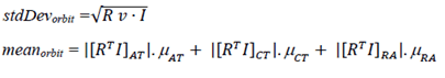 where:
I:
The vector v is expressed in the SSR Orbit Corrections as the three elements in the Variance Orbit Residual Error Vector.
3-D line of sight vector from the user to the satellite in the WGS-84 ECEF coordinate frame.
R:
the rotation matrix from satellite along-track (AT), cross-track (CT) and radial (RA) coordinates into the WGS-84 ECEF coordinate frame. RT denotes the transposed matrix.
v:
the 3-D Orbit error variance vector expressed in satellite along-track, cross-track and radial coordinates.
μ:
the Mean Orbit Error vector expressed in satellite along-track, cross-track and radial coordinates.
8.1.2.1.22 SSR Clock Corrections p. 81
SSR Clock Corrections provides the GNSS receiver with parameters to compute the GNSS satellite clock correction applied to the broadcast satellite clock (see clause 8.1.2.1.7). A polynomial of order 2 describes the clock differences for a certain time period: clock offset, drift, and drift rate.
For integrity purposes, SSR Clock Corrections also provides the correlation time for clock error and clock error rate, and the mean and standard deviation that bounds the residual Clock Error and its associated error rate.
8.1.2.1.23 SSR Code Bias p. 82
SSR Code Bias provides the GNSS receiver with the Code Biases that must be added to the pseudo range measurements of the corresponding code signal to get corrected pseudo ranges. SSR Code Bias contains absolute values, but also enables the alternative use of Differential Code Biases by setting one of the biases to zero. A UE can consistently use signals for which a code bias is transmitted. It is not reliable for a UE to use a signal without retrieving a corresponding code bias from the assistance data message.
For integrity purposes, SSR Code Bias also provides the mean and standard deviation that bounds the residual Code Bias Error and its associated error rate.
8.1.2.1.24 SSR Phase Bias |R16| p. 82
SSR Phase Bias provides the GNSS receiver with the GNSS signal phase bias that are added to the carrier phase measurements of the corresponding signal to get corrected phase ranges. An indicator used to count events when phase bias is discontinuous is provided. An optional indicator is also provided to indicate whether fixed, widelane fixed or float PPP-RTK positioning modes are supported on a per signal basis.
For integrity purposes, SSR Phase Bias also provides the mean and standard deviation that bounds the residual Phase Bias Error and its associated error rate.
8.1.2.1.25 SSR STEC Corrections |R16| p. 82
SSR STEC Corrections provides the GNSS receiver with the parameters to compute the ionosphere slant delay correction based on a variable order polynomial on a per satellite basis and applied to the code and phase measurements.
For integrity purposes, SSR STEC Corrections also provides the ionosphere residual risk parameters, correlation time for ionosposphere range error and range error rate, and the mean and standard deviation that bounds the residual Ionospheric Error and its associated error rate.
8.1.2.1.26 SSR Gridded Correction |R16| p. 82
SSR Gridded Corrections provides the GNSS receiver with STEC residuals and Troposphere delays at a series of correction points and expressed as hydrostatic and wet vertical delays.
For integrity purposes, SSR Gridded Corrections also provides the troposphere residual risk parameters, correlation time for troposphere range error and range error rate, and the mean and standard deviation that bounds the residual Tropospheric Error and associated its error rate in the Vertical Hydro Static Delay and Vertical Wet Delay components.
8.1.2.1.27 SSR URA |R16| p. 82
SSR URA provides the receiver with information about the estimated accuracy of the corrections for each satellite.
8.1.2.1.28 SSR Correction Points |R16| p. 83
The SSR Correction Points provides a list of correction point coordinates or an array of correction points ("grid") for which the SSR Gridded Corrections are valid.
8.1.2.1.29 Integrity Service Parameters |R17| p. 83
Integrity Service Parameters provide the range of Integrity Risk (IR) for which the associated GNSS integrity assistance data is considered to be valid.
8.1.2.1.30 Integrity Alerts |R17| p. 83
Integrity Service Alerts provide information on whether the service can be used for integrity. A Do Not Use (DNU) flag indicates that the corresponding assistance data is not suitable for the purpose of computing integrity. If an Integrity Service Alert is issued and the DNU flag is false, then the corresponding assistance data may be used for the purpose of computing integrity. The DNU flags are defined to be applicable to the specified epoch time only.
8.1.2.1.31 SSR IOD Update |R18| p. 83
SSR IOD Update is used to link assistance data elements based on their Issue of Data (IOD) values, especially for elements which are infrequently updated. The elements with a matching IOD are linked and valid while the SSR IOD Update element is valid, i.e. during the SSR IOD Update and SSR Update Interval and with respect to the IOD SSR.
8.1.2.1.32 SSR Satellite PCV Residuals |R18| p. 83
SSR Satellite Phase Center Variation (PCV) Residuals provide only the nadir angle dependent variations of the satellite APC which can be combined with SSR Orbit Correction and SSR Phase Bias to determine the location of the effective center of the satellite antenna. SSR Satellite PCV Residuals may include residual PCO errors that have not been corrected in the SSR Orbit Correction and SSR Phase Bias.
![]()
![]()
![]()