Content for TS 23.401 Word version: 18.6.0
1…
4…
4.2.2…
4.3…
4.3.6…
4.3.8…
4.3.12…
4.3.16…
4.3.20…
4.3.25…
4.4…
4.6…
4.7…
5…
5.1.2…
5.3…
5.3.2…
5.3.3…
5.3.3.2
5.3.3.3…
5.3.4…
5.3.4B…
5.3.5…
5.3.8…
5.3.9…
5.4…
5.4.4…
5.5…
5.5.1.2…
5.5.2…
5.5.2.2…
5.5.2.3…
5.5.2.4…
5.6…
5.7.3…
5.7A…
5.10
5.11…
5.19…
D…
D.3…
D.3.4
D.3.5
D.3.6
D.3.7…
D.3.8…
E
F…
J…
K…
L…
M…
4.3.20 Relaying function
4.3.21 Core Network assisted eNodeB parameters tuning
4.3.22 UE Power Saving Mode
4.3.23 Access network selection and traffic steering based on RAN-assisted WLAN interworking
4.3.23a Access network selection and traffic steering based on RAN-Controlled WLAN interworking
4.3.24 RAN user plane congestion management function
...
...
4.3.20 Relaying function |R10| p. 77
4.3.20.1 General p. 77
The relaying function enables an operator to improve and extend the coverage area by having a Relay Node (RN) wirelessly connected to an eNodeB serving the RN, called Donor eNodeB (DeNB), via a modified version of the E-UTRA radio interface called the Un interface as specified in TS 36.300.
The relaying function and use of RN/DeNB entities in a network is transparent to the operations of the UEs connected to it and associated core network entities (e.g. MME, S/P-GW, PCRF etc.) for the UEs.
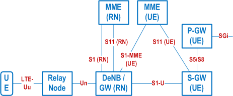
The relaying architecture is shown in Figure 4.3.20.1-1.

The RN supports the eNodeB functionality like termination of the radio protocols of the E-UTRA radio interface and the S1 and X2 interfaces. The RN also supports a subset of the UE functionality and protocols to wirelessly connect to the DeNB.
In addition to supporting eNodeB functionality, the DeNB also embeds and provides the S-GW/P-GW-like functions needed for the RN operation. This includes creating a session for the RN and managing EPS bearers for the RN as shown in clause 4.3.20.3, as well as terminating the S1-AP and S11 interfaces towards the MME serving the RN. Due to the proxy functionality, the DeNB appears as an MME (for S1), an eNodeB (for X2) and an S-GW to the RN.
The RN and DeNB also perform mapping of signalling and data packets onto EPS bearers that are setup for the RN. The mapping is based on existing QoS mechanisms defined for the UE and the P-GW and are described in TS 36.300.
4.3.20.2 RN startup and attach procedure p. 78
4.3.20.2.1 General p. 78
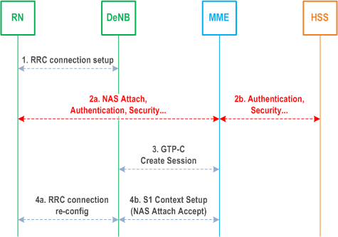
The startup procedure for the Relay Node is based on the normal UE attach procedure and consists of the following two phases:
- Phase I: Attach for RN preconfiguration.
- Phase II: Attach for RN operation (MME of the RN).
4.3.20.2.2 Attach for RN preconfiguration p. 78
The RN attaches to the E-UTRAN/EPC as a UE at power-up (i.e. the RN shall not include the RN indication in the RRC Connection establishment signalling). The eNodeB treats the RN as a normal UE when performing MME selection.
Because the eNodeB does not indicate that this is a RN in the S1 interface Initial UE message, the MME does not perform any further RN specific actions (e.g. it ignores any indication from the HSS that "this subscription includes a permission to operate as a RN").
The authentication of the "RN acting as an UE" is performed by the MME during this attach procedure, using the information obtained from the HSS.
The MME performs the S-GW and P-GW selection as for a normal UE.
The RN retrieves initial RN configuration parameters as user plane traffic, across the SGi reference point, from RN OAM (e.g. list of DeNB cells and selected PLMN).
After this operation is complete, the RN detaches from the network using the normal UE initiated detach procedure, see clause 5.3.8.2.1 and the RN triggers Phase II.
4.3.20.2.3 Attach for RN operation p. 78
To start relay operations, the normal attach procedure, with the following exceptions, is applied:
- The RN and the USIM-RN perform local security operations (e.g. establishment of a secure channel between them) as specified in TS 33.401;
- The RN selects a cell from the list acquired during Phase I;
- The RN establishes an RRC connection with the DeNB, indicating that the connection is for a RN;
- The DeNB is aware of the MMEs that support RN functionality. In all cases when the RN indication is received, the DeNB shall ensure that the current or (re)selected MME supports RN functionality;
- In the S1 interface Initial UE Message, the DeNB sends the RN indication to the MME. This message also carries the IP address of the S-GW/P-GW function embedded in the DeNB;
- The subscription data supplied to the MME by the HSS for USIM-RN includes an indication that the subscription is permitted to be used by a RN.
- If the S1 interface Initial UE Message indicates that this is a RN, but the subscription data does not indicate that the subscription includes a permission to operate as a RN, then the MME shall reject the NAS procedure (e.g. Attach Request, Tracking Area Update Request, Service Request, etc) with an appropriate cause value (e.g. one that avoids retries on this PLMN yet does not harm a RN that has unexpectedly performed PLMN reselection).
- The MME and RN perform the normal EPS Authentication procedures.
- MME (RN) selects the S-GW/P-GW in DeNB for the RN based on the IP address included in the Initial UE Message (i.e. all GW selection and APN related procedures are bypassed during this phase). The MME performs S11 interface signalling with the S-GW/P-GW located in the DeNB;
- The MME accepts the attach procedure and sets up an S1 context with the DeNB.

The detach procedure for the RN is the same as the normal UE detach procedure, though the RN should ensure that no UE is connected to the RN cells before detaching. It is up to RN implementation how it ensures no UE is connected.
4.3.20.3 DeNB E-RAB activation/modification p. 79
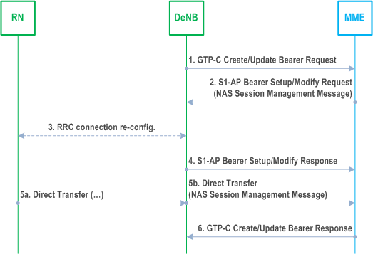
This procedure is used by the DeNB to change the EPS bearer allocation for the RN. The procedure is the same as the normal network-initiated bearer activation/modification procedure with the exception that the S-GW/P-GW functionality (steps 1 and 6) is performed by the DeNB.

4.3.21 Core Network assisted eNodeB parameters tuning |R12| p. 80
4.3.21.1 CN Assistance Information p. 80
Core Network assisted eNodeB parameters tuning aids the eNodeB to minimize the UE state transitions and achieve optimum network behaviour. How the eNodeB uses the Core Network assistance information is not in scope of this specification and is implementation specific.
Core Network assistance information may be derived by the MME per UE in the MME based on collection of UE behaviour statistics or other available information about the expected UE behaviour (such as subscribed APN, IMSI ranges or other subscription information). If the HSS provides the Communication Pattern (CP) parameters (see TS 23.682) within the subscription profile information, then the MME may use the CP parameters for selecting the CN assisted eNodeB parameters. The CP parameters received from the HSS are used by the MME as input to derive the CN assisted eNodeB parameter values. For the case of statistics-based Core Network assistance information collection, this may be enabled based on local configuration (e.g. subscribed APN, IMSI ranges or other subscription information). This information provides the eNodeB with a way to understand the UE behaviour for these aspects:
- "Expected UE activity behaviour", i.e. the expected pattern of the UE's changes between ECM-CONNECTED and ECM-IDLE states. This may be derived e.g. from statistical information or from subscription information.
- "Expected HO interval", i.e. the expected time interval between inter-eNodeB handovers. This may be derived e.g. from statistical information or from subscription information. The "Expected HO interval" parameter is not based on subscription information. Highly mobile UEs may have the ECM-CONNECTED state reduced to reduce handover signalling, unless the activity data do not justify that, as reduced handover signalling would be outweighed by more Service Request signalling).
- "UE Differentiation Information" including the Communication Pattern parameters (see TS 23.682) to support Uu operation optimisation for NB-IoT UE differentiation.
4.3.21.2 Void
4.3.21.3 Core Network Assistance Procedures p. 81
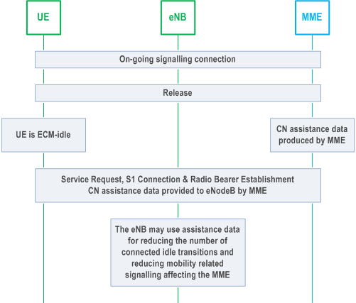
The MME provides CN assistance information to the eNodeB if available, during the setup of the S1 signalling connection (e.g., Attach, Service Request).
The following Figure is a high level description of the transfer of information from an MME to eNodeB during a service request procedure.

4.3.21.4 Wake Up Signal Assistance |R15| p. 82
4.3.21.4.1 General p. 82
The RAN and UE may use a Wake Up Signal (WUS) to reduce the UE's idle mode power consumption. The RAN sends the WUS shortly before the UE's paging occasion. The WUS feature enables UEs to determine that in the paging occasions immediately following their WUS occasion they will not be paged if their WUS is not transmitted, or that they might be paged if their WUS is transmitted (see TS 36.304).
To avoid waking up UEs due to an MME paging other UEs across multiple cells (e.g. due to frequent UE mobility and/or for low paging latency services such as VoLTE), the use of WUS by the eNodeB and the UE is restricted to the last used cell, i.e. the cell in which the UE's RRC connection was last released. To support this:
- WUS-capable eNodeBs should provide the Recommended Cells for Paging IE in the Information On Recommended Cells And eNodeBs For Paging IE (see TS 36.413) to the MME in the S1 UE Context Release Complete or UE Context Suspend Request messages;
- if received during the last S1 UE Context Release Complete or UE Context Suspend Request message, the MME provides (without modification) the Recommended Cells for Paging as Assistance Data for Recommended Cells IE in the S1-AP Paging message to the RAN (see also TS 36.413); and
- the MME shall delete (or mark as invalid) the Information On Recommended Cells And eNodeBs For Paging when a new S1-AP association is established for the UE.
4.3.21.4.2 Group Wake Up Signal |R16| p. 82
To support the Group Wake Up Signal feature, the WUS Assistance Information is used by the eNodeB to help determine the WUS group used when paging the UE (see TS 36.300).
The content of the WUS Assistance Information consists of the paging probability information. The paging probability information provides a metric on the probability of a UE receiving a paging message based on, e.g., statistical information.
The UE may in the Attach Request message provide its capability to support WUS Assistance Information. If WUS Assistance Information is supported, then the UE in the Attach Request or Tracking Area Update message may provide the additional UE paging probability information. The MME may use the UE provided paging probability, local configuration and/or previous statistical information for the UE, when determining the WUS Assistance Information. If the UE supports WUS Assistance Information, the MME may assign WUS Assistance Information to the UE, even when the UE has not provided the additional UE paging probability information.
If the MME has determined WUS Assistance Information for the UE, the MME provides it to the UE in every Attach Accept and/or Tracking Area Update message. The MME stores the WUS Assistance Information parameter in the MM context and provides it to the eNodeB when paging the UE.
UE and MME shall not include WUS Assistance Information in Emergency Attach Request/Attach Accept and in Tracking Area Update/Tracking Area Update Accept messages if the UE has an active emergency PDN connection.
4.3.22 UE Power Saving Mode |R12| p. 82
A UE may adopt a PSM that is described in TS 23.682. If a UE is capable of adopting a PSM and it wants to use the PSM it shall request an Active Time value and may request a Periodic TAU/RAU Timer value during every Attach and TAU procedures, which are handled as described in TS 23.682. The UE shall not request a Periodic TAU/RAU Timer value if it is not requesting an Active Time value. The network shall not allocate an Active Time value if the UE has not requested it.
PSM has no support in the CS domain on the network side.
If the network allocates an Active Time value, the UE and the MME starts the Active timer (see clause 4.3.5.2) with the Active Time value allocated by the network when transitioning from ECM_CONNECTED to ECM_IDLE. The UE shall stop the Active timer, if running, when a transition to ECM_CONNECTED mode is made. When the Active timer expires, the UE deactivates its Access Stratrum functions and enters PSM. In PSM, due to deactivation of Access Stratum functions, the UE stops all idle mode procedures, but continues to run any NAS timers that may apply, e.g. the periodic TAU timer. The UE shall resume Access Stratum functions and idle mode procedures before the periodic TAU timer expires for performing the periodic TAU procedure as applicable. The UE may resume idle mode procedures and Access Stratum functions any time while in PSM, e.g. for mobile originated communications. Any timers and conditions that remain valid during power-off, e.g. for NAS-level back-off, apply in the same way during PSM.
When the Active timer expires for the UE, the MME knows that the UE entered PSM and is not available for paging. The MME handles availability for paging as detailed in clause 4.3.5.2.
On UE side the PSM complies with some substates of EMM_REGISTERED, as specified in TS 24.301. The MME considers the UE to be EMM_REGISTERED, but not reachable. The UE's Access Stratum functions are considered as deactivated during PSM.
For mobile terminated data while a UE is in PSM, the functions for High latency communication may be used as described in clause 4.3.17.7.
When the UE has bearers for emergency services, the UE shall not apply PSM.
When the UE is attached for RLOS services, the UE shall not apply PSM.
4.3.23 Access network selection and traffic steering based on RAN-assisted WLAN interworking |R12| p. 83
As described in TS 36.300, TS 36.304, TS 36.331 and TS 25.331, UTRAN and E-UTRAN may provide RAN assistance parameters to the UE via RRC signalling. The RAN assistance parameters may e.g. include E-UTRAN signal strength and quality thresholds, WLAN channel utilization thresholds, WLAN backhaul data rate thresholds, a list of WLAN identifiers and Offload Preference Indicator (OPI). The UE uses the RAN assistance parameters to perform access network selection and traffic steering decisions between 3GPP access and WLAN using procedures defined in TS 36.304 or using ANDSF policies defined in TS 23.402. Co-existence between the procedures defined in TS 36.304 and ANDSF policies is described in TS 23.402.
For traffic steering decisions using procedures defined in TS 36.304 the MME may provide information to the UE indicating which PDN Connection can be offloaded to WLAN and which PDN Connection shall not be offloaded to WLAN. When provided by the MME, this indication is provided in NAS signalling on a per PDN Connection basis when a PDN Connection is established. The MME may provide a per-RAT indication for the PDN connection, e.g. if the indication is different for UTRAN and for E-UTRAN. If the MME provides a single indication, the UE shall apply such indication both to E-UTRAN and UTRAN.
Traffic steering decisions using procedures defined in TS 36.304 are not applicable to non-seamless WLAN offload (see TS 23.402 for the definition of non-seamless WLAN offload).
In order for the operator to allow/prohibit WLAN offloading on per user and per APN basis, subscription data in the HSS may be configured to indicate if WLAN offload is allowed or prohibited for an APN.
The MME determines the WLAN offloading permissions for the UE and PDN Connection as described below:
- The MME determines the offloadability of a PDN Connection based on subscription data and locally configured policy (e.g. for roaming users or when the subscription data does not include any WLAN offloadability indication).
- When the UE establishes a new PDN Connection, the MME may indicate whether this PDN Connection is offloadable or not offloadable to WLAN.
- The MME may provide an updated WLAN offloadability indication of a PDN Connection to the UE. This may be initiated by HSS as part of the Insert Subscriber Data procedure as described in clause 5.3.9.2. It can also be initiated by the MME by initiating steps 4 to 7 of the Bearer Modification Procedure in clause 5.4.3, Figure 5.4.3-1 or by adding the WLAN offloadability indication to a session management NAS message sent to the UE as part of an existing procedure. The MME shall not trigger signalling to an ECM-IDLE UE solely for the purpose of updating the WLAN offloadability indication.
4.3.23a Access network selection and traffic steering based on RAN-Controlled WLAN interworking |R13| p. 84
As described in TS 36.300 E-UTRAN may support RAN-Controlled WLAN interworking (RCLWI) for controlling traffic steering between E-UTRAN and WLAN for UEs in RRC_CONNECTED. When E-UTRAN sends an "offload" command to the UE, the UE passes an indication to the upper layers indicating that traffic steering to/from WLAN is needed. The upper layers determine to initiate traffic steering to/from WLAN based on the UE capability and the configuration information that has received from NAS layer indicating which PDN connections are offloadable. When the UE receives the "offload" command from the EUTRAN, the UE shall perform handover to WLAN only the PDN connections that have been authorized for offloading.
The NAS level indication about "offloadability" of PDN connections is defined in clause 4.3.23.
The UE uses the RCLWI procedures to perform access network selection and traffic steering decisions between 3GPP access and WLAN or using ANDSF policies defined in TS 23.402. Co-existence between the procedures defined for RCLWI, ANDSF policies and user preference is described in TS 23.402.
4.3.24 RAN user plane congestion management function |R13| p. 84
4.3.24.1 General p. 84
The user plane congestion management function addresses how the system can effectively mitigate RAN user plane congestion in order to reduce the negative impact on the perceived service quality. The congestion mitigation measures include traffic prioritization, traffic reduction and limitation of traffic, and shall be able to manage user plane traffic across a range of variables including the user's subscription, the type of application, and the type of content. Congestion mitigation can be performed in the RAN or in the CN, or in a combined way both in the RAN and in the CN.
4.3.24.2 RAN user plane congestion mitigation in the RAN p. 84
4.3.24.3 RAN user plane congestion mitigation in the CN p. 85
RAN user plane congestion mitigation in the CN uses RAN OAM information, collected by the RAN Congestion Awareness Function (RCAF), to detect congestion. The RAN Congestion Awareness Function is further described in clause 4.4.12. This functionality is applicable only in the case of UTRAN/E-UTRAN accesses.
The RCAF can transfer RAN user plane congestion information (RUCI) to the PCRF over the Np reference point in order to mitigate the congestion by measures selected by the PCRF, as specified in TS 23.203. Decisions to apply congestion mitigation measures may take into account operator policies and subscriber information and all additional available IP-CAN session information.
Different mechanisms and mitigation actions applicable as described in TS 23.203 in order to mitigate RAN User Plane Congestion. Those mechanisms include e.g. service/application gating, service/application bandwidth limitation, deferring of services.