Content for TS 23.401 Word version: 18.6.0
1…
4…
4.2.2…
4.3…
4.3.6…
4.3.8…
4.3.12…
4.3.16…
4.3.20…
4.3.25…
4.4…
4.6…
4.7…
5…
5.1.2…
5.3…
5.3.2…
5.3.3…
5.3.3.2
5.3.3.3…
5.3.4…
5.3.4B…
5.3.5…
5.3.8…
5.3.9…
5.4…
5.4.4…
5.5…
5.5.1.2…
5.5.2…
5.5.2.2…
5.5.2.3…
5.5.2.4…
5.6…
5.7.3…
5.7A…
5.10
5.11…
5.19…
D…
D.3…
D.3.4
D.3.5
D.3.6
D.3.7…
D.3.8…
E
F…
J…
K…
L…
M…
4.2.2 Roaming architecture
4.2.3 Reference points
4.2.4 Warning System architecture
4.2.5 Radio Capability signalling optimization architecture
...
...
4.2.2 Roaming architecture p. 22

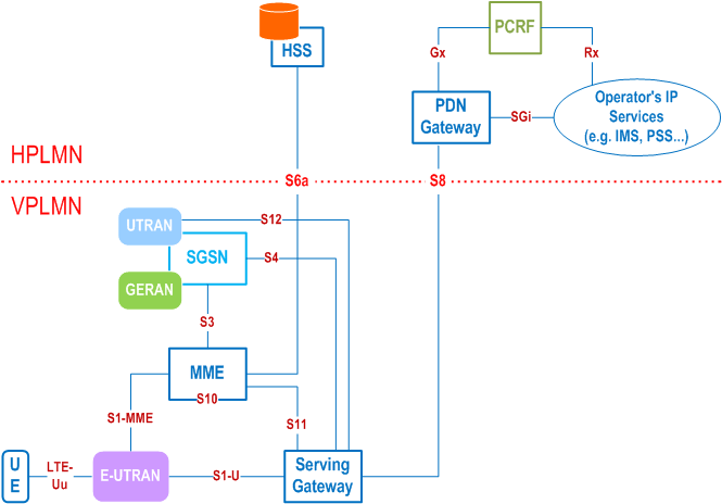
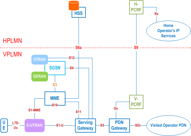
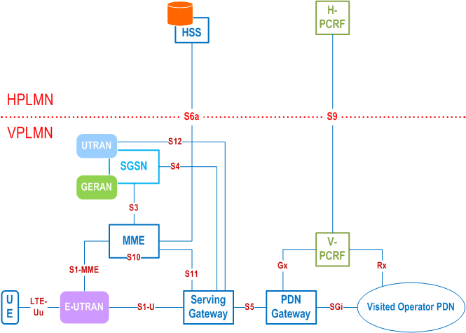
The Figure 4.2.2-2 and Figure 4.2.2-3 represent the Roaming with local breakout case with Application Function (AF) in the Home Network and in the Visited Network respectively. The concurrent use of AF's in the home network and AF's in the visited network is not excluded.


4.2.3 Reference points p. 24
S1-MME:
Reference point for the control plane protocol between E-UTRAN and MME.
S1-U:
Reference point between E-UTRAN and Serving-GW for the per bearer user plane tunnelling and inter eNodeB path switching during handover. S1-U does not apply to the Control Plane CIoT EPS Optimisation.
S3:
It enables user and bearer information exchange for inter 3GPP access network mobility in idle and/or active state. This reference point can be used intra-PLMN or inter-PLMN (e.g. in the case of Inter-PLMN HO).
S4:
It provides related control and mobility support between GPRS Core and the 3GPP Anchor function of Serving-GW. In addition, if Direct Tunnel is not established, it provides the user plane tunnelling.
S5:
It provides user plane tunnelling and tunnel management between Serving-GW and PDN-GW. It is used for Serving-GW relocation due to UE mobility and if the Serving-GW needs to connect to a non-collocated PDN-GW for the required PDN connectivity.
S6a:
It enables transfer of subscription and authentication data for authenticating/authorizing user access to the evolved system (AAA interface) between MME and HSS.
Gx:
It provides transfer of (QoS) policy and charging rules from PCRF to Policy and Charging Enforcement Function (PCEF) in the PDN-GW.
S8:
Inter-PLMN reference point providing user and control plane between the Serving-GW in the VPLMN and the PDN-GW in the HPLMN. S8 is the inter PLMN variant of S5.
S9:
It provides transfer of (QoS) policy and charging control information between the Home PCRF and the Visited PCRF in order to support local breakout function.
S10:
Reference point between MMEs for MME relocation and MME to MME information transfer. This reference point can be used intra-PLMN or inter-PLMN (e.g. in the case of Inter-PLMN HO).
S11:
Reference point providing control plane between MME and Serving-GW. In addition, in order to support Control Plane CIoT EPS Optimisation, the S11-U reference point provides user plane between MME and Serving-GW.
S12:
Reference point between UTRAN and Serving-GW for user plane tunnelling when Direct Tunnel is established. It is based on the Iu-u/Gn-u reference point using the GTP-U protocol as defined between SGSN and UTRAN or respectively between SGSN and GGSN. Usage of S12 is an operator configuration option.
S13:
It enables UE identity check procedure between MME and EIR.
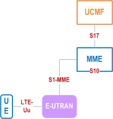
S17:
It enables procedures for RACS between MME and UCMF.
SGi:
It is the reference point between the PDN-GW and the packet data network. Packet data network may be an operator external public or private packet data network or an intra operator packet data network, e.g. for provision of IMS services. This reference point corresponds to Gi for 3GPP accesses.
Rx:
The Rx reference point resides between the AF and the PCRF in the TS 23.203.
When data forwarding is used as part of mobility procedures different user plane routes may be used based on the network configuration (e.g. direct or indirect data forwarding). These routes can be between eNodeB and RNC, eNodeB and SGSN, RNC and S-GW or between S-GW and SGSN. Explicit reference points are not defined for these routes. These user plane forwarding routes can cross inter-PLMN boundaries (e.g. in the case of Inter-PLMN HO).
Protocol assumption:
- The S1-U is based on GTP-U protocol;
- The S3 is based on GTP protocol;
- The S4 and S11 are based on GTP protocol;
- The S5 is based on GTP protocol. PMIP variant of S5 is described in TS 23.402;
- The S8 is based on GTP protocol. PMIP variant of S8 is described in TS 23.402.
- S3, S4, S5, S8, S10 and S11 interfaces are designed to manage EPS bearers as defined in clause 4.7.2.
4.2.4 Warning System architecture p. 25
4.2.5 Radio Capability signalling optimization architecture |R16| p. 26

Figure 4.2.5-1 depicts the EPS architecture supporting RACS. RACS is further described in clause 5.11.3a. EPS architecture supporting provisioning of UCMF is described in TS 23.682.