Content for TS 23.401 Word version: 18.6.0
1…
4…
4.2.2…
4.3…
4.3.6…
4.3.8…
4.3.12…
4.3.16…
4.3.20…
4.3.25…
4.4…
4.6…
4.7…
5…
5.1.2…
5.3…
5.3.2…
5.3.3…
5.3.3.2
5.3.3.3…
5.3.4…
5.3.4B…
5.3.5…
5.3.8…
5.3.9…
5.4…
5.4.4…
5.5…
5.5.1.2…
5.5.2…
5.5.2.2…
5.5.2.3…
5.5.2.4…
5.6…
5.7.3…
5.7A…
5.10
5.11…
5.19…
D…
D.3…
D.3.4
D.3.5
D.3.6
D.3.7…
D.3.8…
E
F…
J…
K…
L…
M…
5.3.9 HSS User Profile management function procedure
5.3.10 Security Function
5.3.11 UE Reachability procedures
5.3.12 Update CSG Location Procedure
5.3.13 CSS subscription data management function procedure
5.3.14 UE Radio Capability Match Request
...
...
5.3.9 HSS User Profile management function procedure p. 241
5.3.9.1 General p. 241
The HSS user profile management function allows the HSS to update the HSS user profile stored in the MME. Whenever the HSS user profile is changed for a user in the HSS, and the changes affect the HSS user profile stored in the MME, the MME shall be informed about these changes by the means of the following procedure:
- Insert Subscriber Data procedure, used to add or modify the HSS user profile in the MME.
5.3.9.2 Insert Subscriber Data procedure p. 242
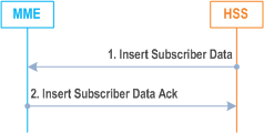
The Insert Subscriber Data procedure is illustrated in Figure 5.3.9.2-1.
Step 1.
The HSS sends an Insert Subscriber Data (IMSI, Subscription Data) message to the MME.
Step 2.
The MME updates the stored Subscription Data and acknowledges the Insert Subscriber Data message by returning an Insert Subscriber Data Ack (IMSI) message to the HSS. The update result should be contained in the Ack message.
The MME initiates appropriate action according to the changed subscriber data (e.g. MME initiates detach if the UE is not allowed to roam in this network). For received PDN subscription contexts that have no related active PDN connection in the MME, no further action is required except storage in the MME. Otherwise if the subscribed QoS Profile has been modified and the UE is in ECM-CONNECTED state or in ECM-IDLE state when ISR is not activated but the UE is reachable by the MME, the HSS Initiated Subscribed QoS Modification procedure, as described in Figure 5.4.2.2-1, is invoked from step 2a. When ISR is not activated and the UE is in ECM-IDLE state and is not reachable by the MME, e.g. when the UE is suspended, when the UE has entered into power saving mode or when the PPF is cleared in the MME, the HSS Initiated Subscribed QoS Modification procedure, as described in Figure 5.4.2.2-1, is invoked from step 2a at the next ECM-IDLE to ECM-CONNECTED transition. If the UE is in ECM-IDLE state and the ISR is activated, this procedure is invoked at the next ECM-IDLE to ECM-CONNECTED transition. If the UE is in ECM-IDLE state and the ISR is not activated and if the subscription change no longer allows the PDN connection, the MME initiated PDN disconnection procedure in clause 5.10.3 is used to delete the concerned PDN connection. If the MME receives RAT specific Subscribed Paging Time Window that is different from the one stored in the MME MM context, the MME updates RAT specific Subscribed Paging Time Window parameter in the MME MM context to the value received from the HSS.
If the UE is in ECM-CONNECTED state and connected via a CSG or hybrid cell, the MME shall check the received CSG subscription data. If the MME detects that the CSG membership to that cell has changed or expired, the MME initiates the procedure in clause 5.16.
If the MME received a changed Service Gap Time parameter in the updated subscription data, the MME shall provide the new Service Gap Time value to the UE in the next Tracking Area Update Accept message, or, if the UE does not send any Tracking Area Update Request within a certain time period that shall be longer than any PSM or eDRX interval used by the UE, the MME may initiate a detach with reattach required of the UE or an RRC connection release with release cause load balancing TAU required of the UE.
5.3.9.3 Purge function p. 242
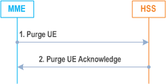
The Purge function allows an MME to inform the HSS that it has deleted the subscription data and MM context of a detached UE. The MME may, as an implementation option, delete the subscription data and MM context of an UE immediately after the implicit or explicit detach of the UE. Alternatively the MME may keep for some time the subscription data and the MM context of the detached UE, so that the data can be reused at a later attach without accessing the HSS.
5.3.10 Security Function p. 243
5.3.10.1 General p. 243
The security functions include:
- Guards against unauthorised EPS service usage (authentication of the UE by the network and service request validation).
- Provision of user identity confidentiality (temporary identification and ciphering).
- Provision of user data and signalling confidentiality (ciphering).
- Provision of origin authentication of signalling and user data (integrity protection).
- Authentication of the network by the UE.
5.3.10.2 Authentication and Key Agreement p. 243
EPS AKA is the authentication and key agreement procedure that shall be used over E-UTRAN, between the UE and MME. EPS AKA is specified in TS 33.401.
5.3.10.3 User Identity Confidentiality p. 243
An M-TMSI identifies a user between the UE and the MME. The relationship between M-TMSI and IMSI is known only in the UE and in the MME.
5.3.10.4 User Data and Signalling Confidentiality p. 243
5.3.10.4.0 General |R17| p. 243
There are two different levels of the security associations between the UE and the network.
- RRC and UP security association is between the UE and E-UTRAN. The RRC security associations protect the RRC signalling between the UE and E-UTRAN (integrity protection and ciphering). The UP security association is between the UE and E-UTRAN and can provide user plane encryption and integrity protection.
- NAS security association is between the UE and the MME. It provides integrity protection and encryption of NAS signalling and, when the Control Plane CIoT EPS Optimisation is used, user data.
5.3.10.4.1 AS security mode command procedure p. 244
The MME triggers the RRC level AS security mode command procedure by sending the needed security parameters to the eNodeB. This enables ciphering of the UP traffic and ciphering and integrity protection of the RRC signalling as described in TS 33.401.
5.3.10.4.2 NAS Security Mode Command procedure p. 244
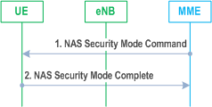
The MME uses the NAS Security Mode Command (SMC) procedure to establish a NAS security association between the UE and MME, in order to protect the further NAS signalling messages. This procedure is also used to make changes in the security association, e.g. to change the security algorithm.
Step 1.
More details of the procedure are described in TS 33.401.
The MME sends NAS Security Mode Command (Selected NAS algorithms, eKSI, ME Identity request, UE Security Capability) message to the UE. ME identity request may be included when NAS SMC is combined with ME Identity retrieval (see clause 5.3.10.5).
Step 2.
The UE responds NAS with Security Mode Complete (NAS-MAC, ME Identity) message. The UE includes the ME Identity if it was requested in step 1.
5.3.10.5 ME identity check procedure p. 245
The Mobile Equipment Identity Check Procedure permits the operator(s) of the MME and/or the HSS and/or the PDN-GW to check the Mobile Equipment's identity (e.g. to check that it has not been stolen, or, to verify that it does not have faults).
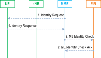
The ME Identity can be checked by the MME passing it to an Equipment Identity Register (EIR) and then the MME analysing the response from the EIR in order to determine its subsequent actions (e.g. sending an Attach Reject if the EIR indicates that the Mobile Equipment is prohibited).
The ME identity check procedure is illustrated in Figure 5.3.10.5-1.
Step 1.
The MME sends Identity Request (Identity Type) to the UE. The UE responds with Identity Response (Mobile Identity).
Step 2.
If the MME is configured to check the IMEI against the EIR, it sends ME Identity Check (ME Identity, IMSI) to EIR. The EIR responds with ME Identity Check Ack (Result).
5.3.11 UE Reachability procedures p. 245
5.3.11.1 General p. 245
There are two procedures necessary for any service related entity that would need to be notified by the reachability of the UE at EPC NAS level:
- UE Reachability Notification Request procedure; and
- UE Activity Notification procedure.
5.3.11.2 UE Reachability Notification Request procedure p. 245
The UE Reachability Notification Request procedure is illustrated in Figure 5.3.11.2-1.

Step 1.
If a service-related entity requests the HSS to provide an indication regarding UE reachability on EPS, the HSS stores the service-related entity and sets the URRP-MME parameter to indicate that such request is received. If the value of URRP-MME parameter has changed from "not set" to "set", the HSS sends a UE-REACHABILITY-NOTIFICATION-REQUEST (URRP-MME) to the MME. If the MME has an MM context for that user, the MME sets URRP-MME to indicate the need to report to the HSS information regarding changes in UE reachability, e.g. when the next NAS activity with that UE is detected.
5.3.11.3 UE Activity Notification procedure p. 246
The UE Activity Notification procedure is illustrated in Figure 5.3.11.3-1.
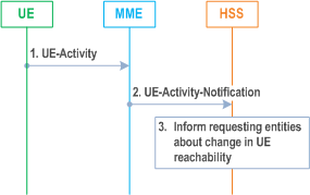
Step 1.
The MME receives an indication regarding UE reachability, e.g. an Attach Request message from the UE or MME receive an indication from S-GW that UE has handed over to non-3GPP coverage.
Step 2.
If the MME contains an MM context of the UE and if URRP-MME for that UE is configured to report once that the UE is reachable, the MME shall send a UE-Activity-Notification (IMSI, UE-Reachable) message to the HSS and clears the corresponding URRP-MME for that UE.
Step 3.
When the HSS receives the UE-Activity-Notification (IMSI, UE-Reachable) message or the Update Location message for an UE that has URRP-MME set, it triggers appropriate notifications to the entities that have subscribed to the HSS for this notification and clears the URRP-MME for that UE.
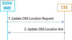
5.3.12 Update CSG Location Procedure |R11| p. 246
The Update CSG Location procedure takes place when the SGSN/MME needs to retrieve the CSG subscription information of the UE from the CSS.
5.3.13 CSS subscription data management function procedure |R11| p. 247
5.3.13.1 General p. 247
The CSS subscription data management function allows the CSS to update the CSS subscription data stored in the MME.
The CSS subscription data is stored and managed in the MME independently from the Subscription Data received from the HSS.
Whenever the CSS subscription data is changed for a user in the CSS, and the changes affect the CSG subscription information stored in the MME, the MME shall be informed about these changes by the means of the following procedure:
- Insert CSG Subscriber Data procedure, used to add or modify the CSS subscription data in the MME.
5.3.13.2 Insert CSG Subscriber Data procedure p. 247
The Insert CSG Subscriber Data procedure is illustrated in Figure 5.3.13.2-1.
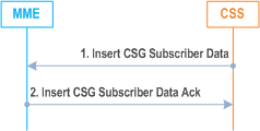
Step 1.
The CSS sends an Insert CSG Subscriber Data (IMSI, CSG Subscription Data) message to the MME.
Step 2.
The MME updates the stored CSG Subscription Data and acknowledges the Insert CSG Subscriber Data message by returning an Insert CSG Subscriber Data Ack (IMSI) message to the CSS. The update result should be contained in the Ack message.
The MME initiates appropriate action according to the changed CSG subscriber data. If the UE is in ECM-CONNECTED state and connected via a CSG or hybrid cell, the MME shall check the received CSG subscriber data. If the MME detects that the CSG membership to that cell has changed or expired, the MME initiates the procedure in clause 5.16.
5.3.14 UE Radio Capability Match Request |R11| p. 247
If the MME, e.g. based on SRVCC capability in NAS, UE Usage Type or local policy, requires more information on the UE radio capabilities support to be able to set the IMS voice over PS Session Supported Indication (see clause 4.3.5.8), then the MME may send a UE Radio Capability Match Request message to the eNodeB. This procedure is typically used during the Initial Attach procedure, during Tracking Area Update procedure for the "first TAU following GERAN/UTRAN Attach" or for "UE radio capability update" or when MME has not received the Voice Support Match Indicator (as part of the MM Context).
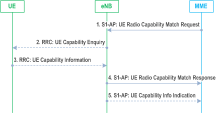
Step 1.
The MME indicates whether the MME wants to receive Voice support match indicator. The MME may include the UE Radio Capability information that it has previously received from the eNodeB via a S1-AP UE CAPABILITY INFO INDICATION as described in clause 5.11.2.
Step 2.
Upon receiving a UE Radio Capability Match Request from the MME, if the eNodeB has not already received the UE radio capabilities from the UE or from MME in step 1, the eNodeB requests the UE to upload the UE radio capability information by sending the RRC UE Capability Enquiry.
Step 3.
The UE provides the eNodeB with its UE radio capabilities sending the RRC UE Capability Information.
Step 4.
The eNodeB checks whether the UE radio capabilities are compatible with the network configuration for ensuring voice service continuity of voice calls initiated in IMS.
For determining the appropriate UE Radio Capability Match Response, the eNodeB is configured by the operator to check whether the UE supports certain capabilities required for Voice continuity of voice calls using IMS PS. In a shared network, the eNodeB keeps a configuration separately per PLMN.
The eNodeB provides a Voice Support Match Indicator to the MME to indicate whether the UE capabilities and networks configuration are compatible for ensuring voice service continuity of voice calls initiated in IMS.
The MME stores the received Voice support match indicator in the MM Context and uses it as an input for setting the IMS voice over PS Session Supported Indication.
Step 5.
If eNodeB requested radio capabilities from UE in step 2 and 3, eNodeB also sends the UE radio capabilities to the MME using the S1-AP UE CAPABILITY INFO INDICATION. The MME stores the UE radio capabilities without interpreting them for further provision to the eNodeB in cases described in clause 5.11.2.