| |
Figure 4.2.1-1 | Non-Roaming Architecture for 3GPP Accesses within EPS using PMIP-based S5 |
Figure 4.2.1-2 | Roaming Architecture for 3GPP Accesses within EPS using PMIP-based S8 |
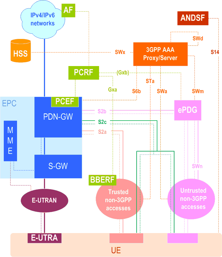
Figure 4.2.2-1 | Non-Roaming Architecture within EPS using S5, S2a, S2b |
Figure 4.2.2-2 | Non-Roaming Architecture within EPS using S5, S2c |
Figure 4.2.3-1 | Roaming Architecture for EPS using S8, S2a- S2b - Home Routed |
Figure 4.2.3-2 | Roaming Architecture for EPS using PMIP-based S8, S2a, S2b (Chained PMIP-based S8-S2a/b) - Home Routed |
Figure 4.2.3-3 | Roaming Architecture for EPS using S8 - S2c - Home Routed |
Figure 4.2.3-4 | Roaming Architecture for EPS using S5, S2a, S2b - Local Breakout |
Figure 4.2.3-5 | Roaming Architecture for EPS using S5, S2c - Local Breakout |
Figure 4.5.7.2.8-1 | EPDG retrieval of WLAN Location Information |
Figure 4.7.1-1 | IPv4 Address Allocation using DHCP with DHCP Server Collocated with the PDN-GW and DHCP Relay in the Serving-GW |
Figure 4.7.1-2 | IPv6 Prefix allocation after the PDN connection setup procedure |
Figure 4.7.2-1 | IPv4 Address Allocation using DHCP with DHCP Server Collocated with the MAG when PDN type is IPv4v6 |
Figure 4.7.6-1 | Prefix Delegation with DHCP Server Collocated with the PDN-GW and DHCP Relay in the Serving-GW when using PMIP-based S5/S8 |
Figure 4.8.1.1-1 | Non-Roaming Architecture for Access Network Discovery Support Functions |
Figure 4.8.1.1-2 | Roaming Architecture for Access Network Discovery Support Functions |
Figure 4.10.3-1 | Two Unicast EPS bearers (PMIP-based S5/S8 and E-UTRAN access) |
Figure 4.10.5.1-1 | Single IPSec SA per PDN connection |
Figure 4.10.5.2-1 | Single IPsec SA per S2b bearer |
Figure 5.1.3.1-1 | Control Plane for PMIP-based S5 and PMIP-based S8 Interfaces |
Figure 5.1.4.1-1 | User Plane for E-UTRAN |
Figure 5.1.4.2-1 | User Plane for A/Gb mode |
Figure 5.1.4.3-1 | User Plane for Iu mode |
Figure 5.1.4.4-1 | User Plane for UTRAN mode and Direct Tunnel on S12 |
Figure 5.2-1 | Initial E-UTRAN attach with PMIP-based S5 or S8 |
Figure 5.3-1 | E-UTRAN Detach Procedure for PMIP-based S5/S8 |
Figure 5.4.1-1 | Dedicated Resource Allocation Procedure, UE in Active Mode |
Figure 5.4.3.2-1 | HSS-initiated Subscribed QoS Modification |
Figure 5.4.5.3-1 | MME-initiated Dedicated Bearer Deactivation |
Figure 5.5-1 | UE-initiated resource request/release with PMIP-based S5/S8 |
Figure 5.6.1-1 | UE requested PDN connectivity with PMIP-based S5 or S8 |
Figure 5.6.2-1 | UE, MME or S-GW initiated PDN disconnection Procedure for PMIP-based S5/S8 |
Figure 5.6.2.2-1 | PDN-GW initiated PDN Disconnection Procedure for PMIP-based S5/S8 |
Figure 5.7.1-1 | Intra-LTE and Inter-eNodeB Handover with Serving-GW Relocation |
Figure 5.7.2-1 | Inter-RAT TAU/RAU or Handover without Serving-GW relocation |
Figure 5.7.2-2 | Inter-RAT TAU/RAU or Handover with Serving-GW Relocation |
Figure 5.9-1 | UE-triggered Service Request for PMIP-based S5/S8 |
Figure 5.11-1 | PDN-GW initiated IPv4 address Delete Procedure |
Figure 5.12-1 | Notification of the ECGI/TAI information changes |
Figure 6.1.1-1 | Protocols for MM control and user planes of S2a for the PMIPv6 option |
Figure 6.1.1-2 | Protocols for MM control and user planes of S2a for the MIPv4 FA mode option |
Figure 6.1.2-1 | Protocols for MM control and user planes of S2c for the DSMIPv6 option |
Figure 6.2.1-1 | Initial attachment with Network-based MM mechanism over S2a for roaming, LBO and non-roaming scenarios |
Figure 6.2.3-1 | Initial attachment when MIPv4 FACoA mode MM mechanism is used over S2a |
Figure 6.2.4-1 | Initial attachment for chained PMIP-based S8-S2a/b roaming scenarios |
Figure 6.3-1 | Initial attachment from Trusted Non-3GPP IP Access with DSMIPv6 |
Figure 6.4.1.1-1 | UE/Trusted Non-3GPP Access Network initiated detach procedure or PDN-disconnection with PMIPv6 |
Figure 6.4.1.2-1 | UE/ePDG/Trusted Non-3GPP Access Network initiated detach procedure for chained PMIP-based S8-S2a/b roaming scenarios and PDN-disconnection for chained PMIP-based S8-S2a |
Figure 6.4.2.1-1 | HSS/AAA-initiated detach procedure with PMIPv6 |
Figure 6.4.2.2-1 | HSS/AAA-initiated detach procedure for chained PMIP-based S8-S2a/b roaming scenarios |
Figure 6.4.3-1 | UE-initiated detach procedure with MIPv4 FACoA |
Figure 6.4.4-1 | Trusted Non-3GPP Access Network initiated detach procedure with MIPv4 FACoA |
Figure 6.4.5-1 | HSS/AAA-initiated detach procedure with MIPv4 FACoA |
Figure 6.5.2-1 | UE-initiated DSMIPv6 PDN disconnection procedure in Trusted Non-3GPP Access Network |
Figure 6.5.3-1 | AAA/HSS-initiated S2c detach procedure in Trusted Non-3GPP Access Network |
Figure 6.5.4-1 | PDN-GW- initiated PDN Disconnection S2c procedure in Trusted Non-3GPP Access Network |
Figure 6.6.1-1 | Network-initiated dynamic policy control procedure in Trusted Non-3GPP IP Access for S2a |
Figure 6.6.2-1 | Network-initiated dynamic policy control for S2c over Trusted Non-3GPP IP Access |
Figure 6.7.1-1 | UE-initiated resource request/release with S2a or S2c |
Figure 6.8.1.1-1 | Additional PDN connectivity with Network-based MM mechanism over S2a for non-roaming and roaming |
Figure 6.8.1.2-1 | Additional PDN connectivity for chained PMIP-based S8-S2a/b roaming scenarios |
Figure 6.8.2-1 | UE-initiated Connectivity to Additional PDN with MIPv4 FACoA on S2a |
Figure 6.8.3-1 | UE-initiated connectivity to multiple PDNs from Trusted Non-3GPP IP Access with DSMIPv6 |
Figure 6.10-1 | PDN-GW reallocation upon attach on S2c |
Figure 6.12.1-1 | PDN-GW Initiated Binding Revocation with S2a PMIP |
Figure 6.12.2-1 | PDN-GW Initiated Registration Revocation over S2a MIPv4 interface |
Figure 6.12.3-1 | PDN-GW Initiated Binding Revocation for Chained PMIP-based S8-S2a Roaming Case |
Figure 6.13-1 | PDN-GW initiated IPv4 address Delete Procedure |
Figure 6.14-1 | Non-3GPP access initiated IPv4 address Delete Procedure |
Figure 6.15-1 | IPv4 Home Address Release Procedure for S2c |
Figure 6.16.1-1 | Enhanced security support activation |
Figure 6.16.2-1 | Enhanced security support de-activation |
Figure 7.1.1-1 | Protocols for MM control and user planes of S2b for the PMIPv6 option |
Figure 7.1.1-2 | Protocols for MM control and user planes of S2b for the GTP option |
Figure 7.1.2-1 | Protocols for MM control and user planes of S2c for the DSMIPv6 option |
Figure 7.2.1-1 | Initial attachment over PMIP based S2b for roaming, non-roaming and LBO |
Figure 7.2.4-1 | Initial attachment over GTP based S2b for roaming, non-roaming and LBO |
Figure 7.2.5-1 | Initial attachment for emergency services over GTP based S2b |
Figure 7.3-1 | Initial attachment from Untrusted Non-3GPP IP Access with DSMIPv6 |
Figure 7.4.1-1 | UE/ePDG-initiated detach procedure with PMIPv6 on S2b |
Figure 7.4.2-1 | HSS/AAA-initiated detach procedure with PMIPv6 on S2b |
Figure 7.4.3-1 | UE/ePDG-initiated detach procedure with GTP on S2b |
Figure 7.4.4-1 | HSS/AAA-initiated detach procedure with GTP on S2b |
Figure 7.5.2-1 | UE-initiated S2c PDN disconnection procedure in Untrusted Non-3GPP Access Network |
Figure 7.5.3-1 | AAA/HSS-initiated S2c detach procedure in Untrusted Non-3GPP Access Network |
Figure 7.5.4-1 | PDN-GW- initiated PDN Disconnection S2c procedure in Untrusted Non-3GPP Access Network |
Figure 7.6.1-1 | UE-initiated connectivity to additional PDN from Un-trusted Non-3GPP IP Access with PMIPv6 |
Figure 7.6.2-1 | UE-initiated connectivity to additional PDN from Un-trusted Non-3GPP IP Access with DSMIPv6 |
Figure 7.6.3-1 | UE-initiated connectivity to additional PDN from Un-trusted Non-3GPP IP Access with GTP |
Figure 7.9-1 | PDN-GW Initiated Resource Allocation Deactivation with PMIPv6 on S2b |
Figure 7.9.2-1 | PDN-GW Initiated Bearer Deactivation with GTP on S2b |
Figure 7.10-1 | Dedicated S2b Bearer Activation Procedure with GTP on S2b |
Figure 7.11.1-1 | S2b Bearer Modification Procedure with GTP on S2b |
Figure 7.11.2-1 | HSS Initiated Subscribed QoS Modification |
Figure 8.2.1.1-1 | Handover from Trusted or Untrusted Non-3GPP IP Access to E-UTRAN with PMIPv6 on S2a or S2b and GTP on S5/S8 interfaces |
Figure 8.2.1.2-1 | Trusted/Untrusted Non-3GPP IP Access to E-UTRAN Handover over PMIP-based S2a and using PMIP-based S5/S8 |
Figure 8.2.1.3-1 | Handover from Trusted/untrusted Non-3GPP IP Access to UTRAN/GERAN with PMIP on S2a and GTP based S5/S8 |
Figure 8.2.1.4-1 | Trusted/untrusted Non-3GPP IP Access to GERAN/UTRAN over PMIP-based S2a and using PMIP-based S5/S8 |
Figure 8.2.2-1 | Handover from 3GPP Access to Trusted Non-3GPP IP Access with PMIPv6 on S2a and PMIPv6 or GTP on S5 interface |
Figure 8.2.3-1 | Handover from 3GPP Access to Untrusted Non-3GPP IP Access with PMIPv6 on S2b |
Figure 8.2.6-1 | Handover from Trusted or Untrusted Non-3GPP IP Access to 3GPP Access with chained S2a/b and PMIP-based S8 |
Figure 8.2.7-1 | Handover from 3GPP IP Access to Trusted or Untrusted Non-3GPP Access with chained S2a/b and PMIP-based S8 |
Figure 8.3-1 | 3GPP IP Access to Non-3GPP IP access Handover over MIPv4-based S2a |
Figure 8.3b-1 | Handover from Trusted Non-3GPP IP Access with MIPv4 FACoA on S2a to 3GPP Access |
Figure 8.4.1-1 | Trusted Non-3GPP S2c (DSMIPv6) to 3GPP with S5 handover |
Figure 8.4.2-1 | 3GPP S5 to Trusted Non-3GPP S2c (DSMIPv6) Handover |
Figure 8.4.3-1 | 3GPP Access to Untrusted Non-3GPP IP Access with S2c (DSMIPv6) Handover |
Figure 8.5.1-1 | Handover between 3GPP Access and trusted / untrusted non-3GPP IP Access with Access Network Discovery and Selection |
Figure 8.6.1.1-1 | Handover from Untrusted Non-3GPP IP Access to E-UTRAN with GTP on S2b and GTP on S5/S8 interfaces |
Figure 8.6.1.2-1 | Handover from Untrusted Non-3GPP IP Access to UTRAN/GERAN with GTP on S2b and GTP on S5/S8 interfaces |
Figure 8.6.2.1-1 | Handover from 3GPP Access to Untrusted Non-3GPP IP Access with GTP on S2b |
Figure 9.1.1-1 | Architecture for optimised handovers between E-UTRAN access and cdma2000 HRPD access (non-roaming case) |
Figure 9.1.1-2 | Architecture for optimised handovers between E-UTRAN access and cdma2000 HRPD access (roaming case; Home routed) |
Figure 9.1.2.3-1 | Protocol Stack for the S101 Reference Point |
Figure 9.1.2.6-1 | Protocol Stack for the S103 Reference Point |
Figure 9.3.1-1 | HRPD registration via LTE/SAE tunnel |
Figure 9.3.2-1 | E-UTRAN to HRPD handover |
Figure 9.4-1 | E-UTRAN to HRPD mobility in idle-mode |
Figure 9.7-1 | S101 tunnel redirection during TAU with MME change |
Figure 9.7-2 | S101 tunnel redirection during inter-eNodeB handover with MME relocation |
Figure 12.1.1-1 | UE Registration Notification |
Figure 12.1.2-1 | AAA-initiated UE De-registration Notification |
Figure 12.1.3-1 | HSS-initiated UE De-registration Notification |
Figure 12.1.4-1 | PDN-GW Address Notification |
Figure 12.1.5-1 | PDN-GW address notification from SGSN/MME |
Figure 12.2.1-1 | HSS-initiated User Profile Update Procedure |
Figure 12.2.2-1 | AAA-initiated Provide User Profile Procedure |
Table 13.1-1 | HSS EPS Data (additional aspects for non 3GPP accesses) |
Table 13.2-1 | MME storage requirements to support optimized interworking with CDMA2000 HRPD |
Table 13.3-1 | S-GW storage requirements to support optimized interworking with CDMA2000 HRPD |
Table 13.5-1 | ePDG Emergency Configuration Data |
Table 13.6-1 | TWAN Emergency Configuration Data |
Figure 15.1-1 | S2c PDN Attach via DSMIPv6 home link |
Figure 16.1.1-1 | Non-roaming architecture for Trusted WLAN access to EPC |
Figure 16.1.1-2 | Roaming architecture for Trusted WLAN access to EPC - Home Routed, VPLMN provides WLAN service |
Figure 16.1.1-3 | Roaming architecture for Trusted WLAN access to EPC - Local break-out |
Figure 16.1.1-4 | Roaming architecture for Trusted WLAN access to EPC - Home routed, HPLMN provides WLAN service |
Figure 16.1.2-1 | Trusted WLAN Access Network functional split |
Figure 16.1.4-1 | Protocols for control and user planes of GTP-based S2a for Transparent Single-Connection mode |
Figure 16.1.4-2 | Protocols for control and user planes of GTP-based S2a for Single-Connection mode |
Figure 16.1.4-3 | Protocols for control and user planes for GTP-based S2a for Multi-Connection mode |
Figure 16.1.6.1-1 | Two Unicast S2a bearers mapped in a single Point-to-Point connection (GTP based S2a) |
Figure 16.1.6.2-1 | Two Unicast S2a bearers mapped to separate WLCP bearers (GTP based S2a) |
Figure 16.2.1-1 | Initial attachment in WLAN on GTP S2a for roaming, LBO and non-roaming scenarios |
Figure 16.2.1a-1 | Initial attachment for Emergency Service in WLAN on GTP S2a for roaming, LBO and non-roaming scenarios |
Figure 16.2.2-1 | Initial attachment in WLAN on PMIP S2a for roaming, LBO and non-roaming scenarios |
Figure 16.2.3 | HSS retrieval of information about an UE from the TWAN |
Figure 16.3.1.1-1 | UE/TWAN Initiated Detach and UE/TWAN requested PDN Disconnection on GTP S2a |
Figure 16.3.1.2-1 | HSS/AAA Initiated Detach on GTP S2a |
Figure 16.3.2.1-1 | UE/TWAN Initiated Detach and UE/ TWAN requested PDN Disconnection on PMIP S2a |
Figure 16.3.2.2-1 | HSS/AAA Initiated Detach on PMIP S2a |
Figure 16.4.1-1 | PDN-GW Initiated Bearer Deactivation with GTP on S2a |
Figure 16.5-1 | Dedicated S2a Bearer Activation Procedure with GTP on S2a |
Figure 16.6.1-1 | PDN-GW-initiated S2a Bearer Modification Procedure with GTP on S2a |
Figure 16.6.2-1 | HSS Initiated Subscribed QoS Modification |
Figure 16.7.1.1-1 | UE/TWAN-Initiated Detach in WLAN on GTP S2a |
Figure 16.7.1.2-1 | HSS/AAA-Initiated Detach in WLAN on GTP S2a |
Figure 16.7.2.1-1 | UE/TWAN Initiated Detach in WLAN on PMIP S2a |
Figure 16.7.2.2-1 | HSS/AAA Initiated Detach in WLAN on PMIP S2a |
Figure 16.8.1-1 | UE-Initiated Connectivity to PDN in WLAN on GTP S2a |
Figure 16.8.2-1 | UE-Initiated Connectivity to PDN in WLAN on PMIP S2a |
Figure 16.9.1-1 | UE/TWAN requested PDN disconnection procedure in WLAN on GTP S2a for Multi-Connection Mode |
Figure 16.9.2-1 | UE/TWAN requested PDN disconnection in WLAN on PMIP S2a for Multi-connection Mode |
Figure 16.10.1.1-1 | Handover in single-connection mode from 3GPP access to Trusted WLAN on GTP S2a for roaming and non-roaming scenarios |
Figure 16.10.1.2-1 | Handover in single-connection mode from 3GPP access to Trusted WLAN on PMIP S2a for roaming and non-roaming scenarios |
Figure 16.10.2.1-1 | Handover from 3GPP access to Trusted WLAN on GTP S2a for roaming and non-roaming scenarios |
Figure 17.1-1 | Basic Network Architecture for E-UTRAN-HRPD Inter-RAT SON Support |
Figure 17.1.2.3-1 | Protocol Stack for S121 Reference Point |
Figure A.1-1 | Direct peering examples: a) PMIP-based VPLMN to GTP-based HPLMN; b) GTP-based VPLMN to PMIP-based HPLMN |
Figure A.1-2 | Direct peering example: Local Breakout, UE from GTP HPLMN Roaming in PMIP VPLMN |
Figure A.1-3 | Direct peering example: Local Breakout, UE from PMIP HPLMN Roaming in GTP VPLMN |
Figure A.2-1 | Roaming Via Interworking Proxy: a) GTP-based HPLMN to PMIP-based VPLMN; b) PMIP-based HPLMN to GTP-based VPLMN |
Figure C.2-1 | Trusted non-3GPP to Trusted non-3GPP handover based on S2c |
Figure C.3-1 | S2b to S2a (PMIPv6) Handover |
Figure C.4-1 | S2c over trusted or untrusted Non-3GPP IP access to S2a (PMIPv6) Handover |
Figure C.5-1 | Message flow for handover between two untrusted non-3GPP IP accesses based on MOBIKE |
Figure E.1-1 | Gateway Relocation when PMIPv6 MM mechanism is used over S2a |
Figure E.2-1 | Gateway Relocation when MIPv4 FACoA mode MM mechanism is used over S2a |