Figure 4-1 | Overview of the security architecture |
Figure 6.1.1-1 | Successful EPS AKA authentication |
Figure 6.1.2-1 | Distribution of authentication data from HE to MME |
Figure 6.1.3-1 | User identity query |
Figure 6.1.4-1 | Distribution of IMSI and authentication data within one serving domain |
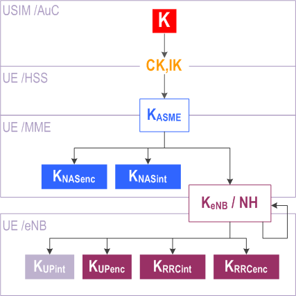
Figure 6.2-1 | Key hierarchy in E-UTRAN |
Figure 6.2-2 | Key distribution and key derivation scheme for EPS (in particular E-UTRAN) for network nodes. |
Figure 6.2-3 | Key derivation scheme for EPS (in particular E-UTRAN) for the ME. |
Figure 7.2.4.4-1 | NAS Security Mode Command procedure |
Figure 7.2.4.5-1 | AS security setup |
Figure 7.2.8.1-1 | Model for the handover key chaining |
Figure 7.3.4-1 | User plane (UP) integrity protection activation mechanism |
Figure 7.5-1 | eNB periodic local authentication procedure |
Figure 9.2.2.1-1 | Handover from UTRAN to E-UTRAN |
Figure 14.3.1-1 | SRVCC handover from UTRAN/GERAN to E-UTRAN. Key derivations in the Figure are only shown for UMTS subscribers. |
Figure A.2-1 | Encoding of SN id as an octet string |
Table A.7-1 | Algorithm type distinguishers |
Figure B.1-1 | Ciphering of data |
Figure B.2-1 | Derivation of MAC-I/NAS-MAC (or XMAC-I/XNAS-MAC) |
Figure E.1.2-1 | Dual Connectivity architecture with an SeNB |
Figure E.1.3-1 | Offload architecture for EN-DC |
Figure E.2.3-1 | SeNB encryption/decryption activation |
Figure E.2.4.2-1 | Addition to the Key Hierarchy for the SeNB |
Figure E.3.3-1 | SgNB encryption/decryption and integrity protection activation |
Figure E.3.4.2-1 | Addition to the Key Hierarchy for the SgNB |
Figure G.1-1 | LWA architecture |
Figure G.2.4.2-1 | S-KWT computation |
Figure G.3-1 | 3GPP vendor specific EAP-LWA method |
Figure H.1-1 | LTE-WLAN integration architecture using IPsec tunnelling |
Figure H.1-2 | LTE-WLAN integration using IPsec tunnelling protocol stack |
Figure H.4.1-1 | LWIP-PSK Derivation |
Figure K.1-1 | IAB architecture when IAB-node is using EN-DC |
Figure K.2-1 | Summary of authentication and authorization of IAB-nodes |