Content for TS 23.401 Word version: 18.6.0
1…
4…
4.2.2…
4.3…
4.3.6…
4.3.8…
4.3.12…
4.3.16…
4.3.20…
4.3.25…
4.4…
4.6…
4.7…
5…
5.1.2…
5.3…
5.3.2…
5.3.3…
5.3.3.2
5.3.3.3…
5.3.4…
5.3.4B…
5.3.5…
5.3.8…
5.3.9…
5.4…
5.4.4…
5.5…
5.5.1.2…
5.5.2…
5.5.2.2…
5.5.2.3…
5.5.2.4…
5.6…
5.7.3…
5.7A…
5.10
5.11…
5.19…
D…
D.3…
D.3.4
D.3.5
D.3.6
D.3.7…
D.3.8…
E
F…
J…
K…
L…
M…
5.5.2.3 E-UTRAN to GERAN A/Gb mode Inter RAT handover
5.5.2.3.1 General
5.5.2.3.2 Preparation phase
5.5.2.3.3 Execution phase
5.5.2.3.4 E-UTRAN to GERAN A/Gb mode Inter RAT handover reject
...
...
5.5.2.3 E-UTRAN to GERAN A/Gb mode Inter RAT handover p. 303
5.5.2.3.1 General p. 303
The procedure is based on Packet-switched handover for GERAN A/Gb mode defined in TS 43.129.
Pre-conditions:
- The UE is in ECM-CONNECTED state (E-UTRAN mode);
- The BSS must support PFM, Packet Flow Management, procedures.
5.5.2.3.2 Preparation phase p. 304
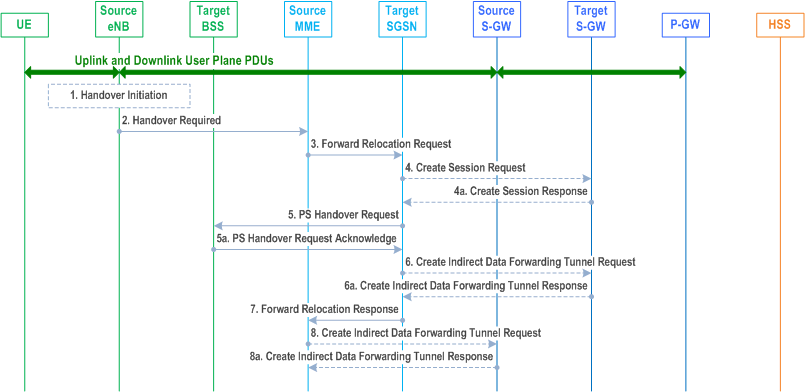
Step 1.
The source eNodeB decides to initiate an Inter RAT Handover to the target GERAN A/Gb mode (2G) system. At this point both uplink and downlink user data is transmitted via the following: Bearer(s) between UE and Source eNodeB, GTP tunnel(s) between Source eNodeB, Serving-GW and PDN-GW.
If the UE has an ongoing emergency bearer service the source eNodeB shall not initiate PS handover to GERAN.
Step 2.
The source eNodeB sends a Handover Required (S1AP Cause, Target System Identifier, Source to Target Transparent Container) message to the Source MME to request the CN to establish resources in the Target BSS, Target SGSN and the Serving-GW. The bearers that will be subject to data forwarding (if any) are identified by the target SGSN in a later step (see step 7 below).
The 'Target System Identifier' IE contains the identity of the target global cell Id.
Step 3.
The Source MME determines from the 'Target System Identifier' IE that the type of handover is IRAT Handover to GERAN A/Gb mode. The Source MME selects the Target SGSN as described in clause 4.3.8.4 on "SGSN Selection Function". The Source MME initiates the Handover resource allocation procedure by sending a Forward Relocation Request (IMSI, Target Identification (shall be set to "empty"), MM Context, PDN Connections, MME Tunnel Endpoint Identifier for Control Plane, MME Address for Control plane, Source to Target Transparent Container, Packet Flow ID, XID parameters (if available), Target Cell Identification, MS Info Change Reporting Action (if available), CSG Information Reporting Action (if available), UE Time Zone, ISR Supported, RAN Cause, Serving Network) message to the target SGSN. If the information ISR Supported is indicated, this indicates that the source MME and associated Serving-GW are capable to activate ISR for the UE. When ISR is activated the message should be sent to the SGSN that maintains ISR for the UE when this SGSN is serving the target identified by the Target Identification. This message includes all PDN Connections active in the source system and for each PDN Connection includes the associated APN, the address and the uplink Tunnel endpoint parameters of the Serving-GW for control plane, and a list of EPS Bearer Contexts. The old Serving Network is sent to target MME to support the target MME to resolve if Serving Network is changed. In network sharing scenarios Serving Network denotes the serving core network.
The MM context includes information on the EPS Bearer context(s). If none of the UE's EPS Bearers can be supported by the selected target SGSN, the source MME rejects the handover attempt by sending a Handover Preparation Failure (Cause) message to the Source eNodeB.
The target SGSN maps the EPS bearers to PDP contexts 1-to-1 and maps the EPS Bearer QoS parameter values of an EPS bearer to the Release 99 QoS parameter values of a bearer context as defined in Annex E.
Prioritization of PDP Contexts is performed by the target core network node, i.e. target SGSN.
If the Source MME supports IRAT Handover to GERAN A/Gb procedure it has to allocate a valid PFI during the bearer activation procedure. RAN Cause indicates the S1AP Cause as received from the source eNodeB. The Source to Target Transparent Container includes the value from the Source to Target Transparent Container received from the source eNodeB.
The MM context contains security related information, e.g. supported ciphering algorithms, as described in TS 29.274. Handling of security keys is described in TS 33.401.
The target SGSN selects the ciphering algorithm to use. This algorithm will be sent transparently from the target SGSN to the UE in the NAS container for Handover (part of the Target to Source Transparent Container). The IOV-UI parameter, generated in the target SGSN, is used as input to the ciphering procedure and it will also be transferred transparently from the target SGSN to the UE in the NAS container for Handover. More details are described in TS 33.401.
When the target SGSN receives the Forward Relocation Request message the required EPS Bearer, MM, SNDCP and LLC contexts are established and a new P-TMSI is allocated for the UE. When this message is received by the target SGSN, it begins the process of establishing PFCs for all EPS Bearer contexts.
When the target SGSN receives the Forward Relocation Request message it extracts from the EPS Bearer Contexts the NSAPIs and SAPIs and PFIs to be used in the target SGSN. If for a given EPS Bearer Context the target SGSN does not receive a PFI from the source MME, it shall not request the target BSS to allocate TBF resources corresponding to that EPS Bearer Context. If none of the EPS Bearer Contexts forwarded from the source MME has a valid PFI allocated the target SGSN shall consider this as a failure case and the request for Handover shall be rejected.
If when an SAPI and PFI was available at the source MME but the target SGSN does not support the same SAPI and PFI for a certain NSAPI as the source MME, the target SGSN shall continue the Handover procedure only for those NSAPIs for which it can support the same PFI and SAPI as the source MME. All EPS Bearer contexts for which no resources are allocated by the target SGSN or for which it cannot support the same SAPI and PFI (i.e. the corresponding NSAPIs are not addressed in the response message of the target SGSN), are maintained and the related SAPIs and PFIs are kept. These EPS Bearer contexts may be modified or deactivated by the target SGSN via explicit SM procedures upon RAU procedure.
The source MME shall indicate the current XID parameter settings if available (i.e. those XID parameters received during a previous IRAT Handover procedure) to the target SGSN. If the target SGSN can accept all XID parameters as indicated by the source MME, the target SGSN shall create a NAS container for Handover indicating 'Reset to the old XID parameters'. Otherwise, if the target SGSN cannot accept all XID parameters indicated by the source MME or if no XID parameters were indicated by the source MME, the target SGSN shall create a NAS container for Handover indicating Reset (i.e. reset to default parameters).
The target SGSN shall determine the Maximum APN restriction based on the APN Restriction of each bearer context received in the Forward Relocation Request, and shall subsequently store the new Maximum APN restriction value.
If SIPTO at the Local Network is active for a PDN connection in the architecture with stand-alone GW the source MME shall include the Local Home Network ID of the source cell in the PDN Connections corresponding to the SIPTO at the Local Network PDN connection.
Step 4.
The target SGSN determines if the Serving-GW is to be relocated, e.g., due to PLMN change. If the Serving-GW is to be relocated, the target SGSN selects the target Serving-GW as described under clause 4.3.8.2 on "Serving-GW selection function", and sends a Create Session Request message (IMSI, SGSN Tunnel Endpoint Identifier for Control Plane, SGSN Address for Control plane, PDN-GW address(es) for user plane, PDN-GW UL TEID(s) for user plane, PDN-GW address(es) for control plane, and PDN-GW TEID(s) for control plane, the Protocol Type over S5/S8, Serving Network) per PDN connection to the target Serving-GW. The Protocol Type over S5/S8 is provided to Serving-GW which protocol should be used over S5/S8 interface.
Step 4a.
The target Serving-GW allocates its local resources and returns a Create Session Response (Serving-GW address(es) for user plane, Serving-GW UL TEID(s) for user plane, Serving-GW Address for control plane, Serving-GW TEID for control plane) message to the target SGSN.
Step 5.
The target SGSN establishes the EPS Bearer context(s) in the indicated order. The SGSN deactivates, as provided in step 9 of the execution phase, the EPS Bearer contexts which cannot be established.
The Target SGSN requests the Target BSS to establish the necessary resources (PFCs) by sending the message PS Handover Request (Local TLLI, IMSI, Cause, Target Cell Identifier, PFCs to be set-up list, Source RNC to Target BSS Transparent Container and NAS container for handover). The target SGSN shall not request resources for which the Activity Status Indicator within a EPS Bearer Context indicates that no active bearer exists on the source side for that PDP context. The Cause indicates the RAN Cause as received from the source MME. The Source RNC to Target BSS Transparent Container contains the value from the Source to Target Transparent Container received from the source MME. All EPS Bearer Contexts indicate active status because E-UTRAN does not support selective RAB handling.
Based upon the ABQP for each PFC the target BSS makes a decision about which PFCs to assign radio resources. The algorithm by which the BSS decides which PFCs that need resources is implementation specific. Due to resource limitations not all downloaded PFCs will necessarily receive resource allocation. The target BSS allocates TBFs for each PFC that it can accommodate.
The target BSS shall prepare the 'Target to Source Transparent Container' which contains a PS Handover Command including the EPC part (NAS container for Handover) and the RN part (Handover Radio Resources).
Step 5a.
The Target BSS allocates the requested resources and returns the applicable parameters to the Target SGSN in the message PS Handover Request Acknowledge (Local TLLI, List of set-up PFCs, Target BSS to Source RNC Transparent Container, Cause). Upon sending the PS Handover Request Acknowledge message the target BSS shall be prepared to receive downlink LLC PDUs from the target SGSN for the accepted PFCs.
Any EPS Bearer contexts for which a PFC was not established are maintained in the target SGSN and the related SAPIs and PFIs are kept. These EPS Bearer contexts shall be deactivated by the target SGSN via explicit SM procedures upon the completion of the routing area update (RAU) procedure.
Step 6.
If indirect forwarding and relocation of Serving-GW applies the target SGSN sends a Create Indirect Data Forwarding Tunnel Request message (Target SGSN Address(es) and TEID(s) for DL data forwarding) to the Serving-GW used for indirect packet forwarding.
Indirect forwarding may be performed via a Serving-GW which is different from the Serving-GW used as the anchor point for the UE.
Step 6a.
The Serving-GW returns a Create Indirect Data Forwarding Tunnel Response (Cause, Serving-GW DL Address(es) and TEID(s) for data forwarding) message to the target SGSN.
Step 7.
The Target SGSN sends the message Forward Relocation Response (Cause, SGSN Tunnel Endpoint Identifier for Control Plane, SGSN Address for Control Plane, Target to Source Transparent Container, RAN Cause, List of set-up PFIs, Address(es) and TEID(s) for User Traffic Data Forwarding, Serving-GW change indication) to the Source MME. Serving-GW change indication indicates a new Serving-GW has been selected. RAN Cause indicates the Cause as received from the target BSS. The Target to Source Transparent Container includes the value from the Target BSS to Source RNC Transparent Container received from the target BSS.
If 'Indirect Forwarding' and relocation of Serving-GW applies, then the IEs 'Address(es) and TEID(s) for User Traffic Data Forwarding' contain the DL GTP-U tunnel endpoint parameters received in step 6a. Otherwise the IEs 'Address(es) and TEID(s) for User Traffic Data Forwarding' contains the DL GTP-U tunnel endpoint parameters to the Target SGSN.
The target SGSN activates the allocated LLC/SNDCP engines as specified in TS 44.064 for an SGSN originated Reset or 'Reset to the old XID parameters'.
Step 8.
If "Indirect Forwarding" applies, the Source MME sends the message Create Indirect Data Forwarding Tunnel Request (Address(es) and TEID(s) for Data Forwarding (received in step 7)) to the Serving-GW used for indirect packet forwarding.
Indirect forwarding may be performed via a Serving-GW which is different from the Serving-GW used as the anchor point for the UE.
Step 8a.
The Serving-GW returns the forwarding user plane parameters by sending the message Create Indirect Data Forwarding Tunnel Response (Cause, Serving-GW Address(es) and TEID(s) for Data Forwarding). If the Serving-GW doesn't support data forwarding, an appropriate cause value shall be returned and the Serving-GW Address(es) and TEID(s) will not be included in the message.
5.5.2.3.3 Execution phase p. 308
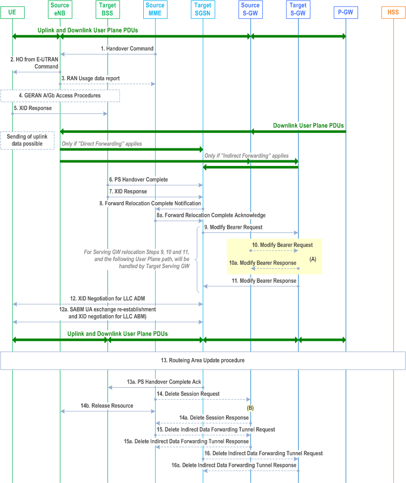
The source eNodeB continues to receive downlink and uplink user plane PDUs.
Step 1.
The Source MME completes the preparation phase towards Source eNodeB by sending the message Handover Command (Target to Source Transparent Container (PS Handover Command with RN part and EPC part), E-RABs to Release List, Bearers Subject to Data Forwarding List), S1AP Cause. The "Bearers Subject to Data forwarding list" may be included in the message and it shall be a list of 'Address(es) and TEID(s) for user traffic data forwarding' received from target side in the preparation phase (Step 7 of the preparation phase for Direct Forwarding, else parameters received in Step 8a of the preparation phase). S1AP Cause indicates the RAN Cause as received from the target SGSN.
Source eNodeB initiate data forwarding for the bearers specified in the "Bearers Subject to Data Forwarding List". The data forwarding may go directly i.e. to target SGSN or alternatively go via the Serving-GW if so decided by source MME and/or target SGSN in the preparation phase.
Step 2.
The Source eNodeB will give a command to the UE to handover to the Target Access System via the message HO from E-UTRAN Command. This message includes a transparent container including radio aspect parameters that the Target BSS has set-up in the preparation phase (RN part). This message also includes the XID and IOV-UI parameters received from the Target SGSN (EPC part).
Upon the reception of the HO from E-UTRAN Command message containing the Handover Command message, the UE shall associate its bearer IDs to the respective PFIs based on the relation with the NSAPI and shall suspend the uplink transmission of the user plane data.
Step 3.
If the PLMN has configured Secondary RAT usage data reporting and the source eNodeB has Secondary RAT usage data to report, the eNodeB sends the RAN Usage data report message (Secondary RAT usage data) to the MME. Since the handover is an inter-RAT handover, the MME continues with the Secondary RAT usage data reporting procedure as in clause 5.7A.3. The reporting procedure in clause 5.7A.3 is only performed if PGW secondary RAT usage reporting is active.
Step 4.
The UE moves to the Target GERAN A/Gb (2G) system and performs executes the handover according to the parameters provided in the message delivered in step 2. The procedure is the same as in step 6 in clause 5.3.2.2 of TS 43.129 with the additional function of association of the received PFI and existing Bearer Id related to the particular NSAPI.
Step 5.
After accessing the cell using access bursts and receiving timing advance information from the BSS in step 4, the UE processes the NAS container and then sends one XID response message to the target SGSN via target BSS. The UE sends this message immediately after receiving the Packet Physical Information message containing the timing advance or, in the synchronised network case, immediately if the PS Handover Access message is not required to be sent.
Upon sending the XID Response message, the UE shall resume the user data transfer only for those NSAPIs for which there are radio resources allocated in the target cell. For NSAPIs using LLC ADM, for which radio resources were not allocated in the target cell, the UE may request for radio resources using the legacy procedures.
If the Target SGSN indicated XID Reset (i.e. reset to default XID parameters) in the NAS container included in the HO from E-UTRAN Command message, and to avoid collision cases the mobile station may avoid triggering XID negotiation for any LLC SAPI used in LLC ADM, but wait for the SGSN to do so (see step 12). In any case the mobile station may avoid triggering XID negotiation for any LLC SAPI used in LLC ABM, but wait for the SGSN to do so (see step 12a).
This step is the same as specified in clause 5.3.2.2 in TS 43.129.
Step 6.
Upon reception of the first correct RLC/MAC block (sent in normal burst format) from the UE to the Target BSS, the Target BSS informs the Target SGSN by sending the message PS Handover Complete (IMSI, and Local TLLI, Request for Inter RAT Handover Info). The target BSS that supports inter-RAT PS handover to UTRAN shall, when the INTER RAT HANDOVER INFO was not included in the Source BSS to Target BSS transparent container received in the PS HANDOVER REQUEST message as specified in TS 48.018, request the INTER RAT HANDOVER INFO from the target SGSN by setting the 'Request for Inter RAT Handover Info' to '1'.
Step 7.
The Target BSS also relays the message XID Response to the Target SGSN. Note, the message in step 6 and 7 may arrive in any order in the Target SGSN.
Step 8.
Then the Target SGSN knows that the UE has arrived to the target side and Target SGSN informs the Source MME by sending the Forward Relocation Complete Notification (ISR Activated, Serving-GW change) message. If ISR Activated is indicated, the source MME shall maintain the UE's contexts and activate ISR, which is only possible when the S-GW is not changed. The Source MME will also acknowledge that information. A timer in source MME is started to supervise when resources in Source eNodeB and Source Serving-GW (for Serving-GW relocation) shall be released.
Upon receipt of the Forward Relocation Complete Acknowledge message the target SGSN starts a timer if the target SGSN allocated S-GW resources for indirect forwarding.
For all bearers that were not included in the Forward Relocation Request message sent in step 3, the MME now releases them by sending a Delete Bearer Command to the SGW, or, the appropriate message to the SCEF.
Step 9.
The Target SGSN will now complete the Handover procedure by informing the Serving-GW (for Serving-GW relocation this will be the Target Serving-GW) that the Target SGSN is now responsible for all the EPS Bearer Context(s) the UE has established. This is performed in the message Modify Bearer Request (SGSN Tunnel Endpoint Identifier for Control Plane, NSAPI(s), SGSN Address for Control Plane, SGSN Address(es) and TEID(s) for User Traffic for the accepted EPS bearers and RAT type, ISR Activated) per PDN connection. As it is a mobility from E-UTRAN, if the target SGSN supports location information change reporting, the target SGSN shall include the User Location Information (according to the supported granularity) in the Modify Bearer Request, regardless of whether location information change reporting had been requested in the previous RAT by the PDN-GW. If the PDN-GW requested User CSG information (determined from the UE context), the SGSN also includes the User CSG Information IE in this message. If the UE Time Zone has changed, the SGSN includes the UE Time Zone IE in this message. If Serving-GW is not relocated but the Serving Network has changed or if the SGSN has not received any old Serving Network information from the old MME, the SGSN includes the new Serving Network IE in this message. In network sharing scenarios Serving Network denotes the serving core network. If indicated, ISR Activated indicates that ISR is activated, which is only possible when the S-GW was not changed. When the Modify Bearer Request does not indicate ISR Activated and S-GW is not changed, the S-GW deletes any ISR resources by sending a Delete Bearer Request to the other CN node that has bearer resources on the S-GW reserved.
The SGSN releases the non-accepted EPS Bearer contexts by triggering the EPS Bearer context deactivation procedure. If the Serving-GW receives a DL packet for a non-accepted bearer, the Serving-GW drops the DL packet and does not send a Downlink Data Notification to the SGSN.
Step 10.
The Serving-GW (for Serving-GW relocation this will be the Target Serving-GW) may inform the PDN-GW the change of, for example, for Serving-GW relocation or the RAT type, that e.g. can be used for charging, by sending the message Modify Bearer Request per PDN connection. The S-GW also includes User Location Information IE and/or UE Time Zone IE and/or User CSG Information IE if they are present in step 9. Serving Network should be included if it is received in step 9 or in step 4 in clause 5.5.2.3.2. For Serving-GW relocation, the Serving-GW allocates DL TEIDs on S5/S8 even for non-accepted bearers and may include the PDN Charging Pause Supported Indication. The PDN-GW must acknowledge the request with the message Modify Bearer Response. In the case of Serving-GW relocation, the PDN-GW updates its context field and returns a Modify Bearer Response (Charging Id, MSISDN, PDN Charging Pause Enabled Indication (if PDN-GW has chosen to enable the function), etc.) message to the Serving-GW. The MSISDN is included if the PDN-GW has it stored in its UE context. If location information change reporting is required and supported in the target SGSN, the PDN-GW shall provide MS Info Change Reporting Action in the Modify Bearer Response.
If PCC infrastructure is used, the PDN-GW informs the PCRF about the change of, for example, the RAT type.
If the Serving-GW is relocated, the PDN-GW shall send one or more "end marker" packets on the old path immediately after switching the path. The source Serving-GW shall forward the "end marker" packets to the source eNodeB.
Step 11.
The Serving-GW (for Serving-GW relocation this will be the Target Serving-GW) acknowledges the user plane switch to the Target SGSN via the message Modify Bearer Response (Cause, Serving-GW Tunnel Endpoint Identifier for Control Plane, Serving-GW Address for Control Plane, Protocol Configuration Options, MS Info Change Reporting Action). At this stage the user plane path is established for all EPS Bearer contexts between the UE, Target BSS, Target SGSN, Serving-GW (for Serving-GW relocation this will be the Target Serving-GW) and PDN-GW.
If the Serving-GW does not change, the Serving-GW shall send one or more "end marker" packets on the old path immediately after switching the path.
Step 12.
If the Target SGSN indicated XID Reset (i.e. reset to default XID parameters) in the NAS container included in the HO from E-UTRAN Command message, then on receipt of the PS Handover Complete the Target SGSN initiates an LLC/SNDCP XID negotiation for each LLC SAPI used in LLC ADM. In this case if the Target SGSN wants to use the default XID parameters, it shall send an empty XID Command. If the Target SGSN indicated 'Reset to the old XID parameters' in the NAS container, no further XID negotiation is required for LLC SAPIs used in LLC ADM only.
Step 12a.
The Target SGSN (re-)establishes LLC ABM for the EPS Bearer contexts which use acknowledged information transfer. During the exchange of SABM and UA the SGSN shall perform LLC/SNDCP XID negotiation.
These steps (12 and 12a) are the same as specified in clause 5.3.2.2 in TS 43.129.
Step 13.
After the UE has finished the reconfiguration procedure the UE shall initiate the Routing Area Update procedure.
The target SGSN knows that an IRAT Handover has been performed for this UE as it received the bearer context(s) by handover messages and therefore the target SGSN performs only a subset of the RAU procedure, specifically it excludes the context transfer procedures between source MME and target SGSN.
For a UE supporting CIoT EPS Optimisations, the UE uses the bearer status information in the RAU Accept to identify any non-transferred bearers that it shall locally release.
Step 13a.
Upon reception of the PS Handover Complete message with the 'Request for Inter RAT Handover Info' set to '1', the SGSN should send then PS Handover Complete Acknowledge (TLLI, INTER RAT HANDOVER INFO) to the target BSS.
The target BSS receiving the PS Handover Complete Acknowledge message shall set the 'Reliable INTER RAT HANDOVER' to '1' in the PS Handover Required message in any subsequent PS handover to GERAN A/Gb mode. The target BSS failing to receive the PS Handover Complete Acknowledge message shall set the 'Reliable INTER RAT HANDOVER' to '0' in the PS Handover Required message in any subsequent PS handover to GERAN A/Gb mode. The Target BSS shall, upon receipt of the INTER RAT HANDOVER INFO in the PS Handover Complete Acknowledge message, overwrite its current INTER RAT HANDOVER INFO with this new one.
Step 14.
When the timer started at step 8 expires, the source MME sends a Release Resources message to the source eNodeB. The Source eNodeB releases its resources related to the UE.
When the timer started in step 8 expires and if the source MME received the Serving-GW change indication in the Forward Relocation Response message, it deletes the EPS bearer resources by sending Delete Session Request (Cause, Operation Indication, Secondary RAT usage data) messages to the Source Serving-GW. The operation Indication flag is not set, that indicates to the Source Serving-GW that the Serving-GW changes and the Source Serving-GW shall not initiate a delete procedure towards the PDN-GW. Secondary RAT usage data is included if it was received in step 3. The Source Serving-GW acknowledges with Delete Session Response (Cause) messages. If ISR has been activated before this procedure, the cause indicates to the Source S-GW that the Source S-GW shall delete the bearer resources on the other old CN node by sending Delete Bearer Request message(s) to that CN node.
Step 15.
If indirect forwarding was used then the expiry of the timer at source MME started at step 8 triggers the source MME to send a Delete Indirect Data Forwarding Tunnel Request message to the S-GW to release the temporary resources used for indirect forwarding.
Step 16.
If indirect forwarding was used and the Serving-GW is relocated, then the expiry of the timer at target SGSN started at step 8 triggers the target SGSN to send a Delete Indirect Data Forwarding Tunnel Request message to the target S-GW to release temporary resources used for indirect forwarding.
5.5.2.3.4 E-UTRAN to GERAN A/Gb mode Inter RAT handover reject p. 311
The Target BSS may reject the use of the Handover procedure if none of the requested PFCs in the PS Handover Request message could be established. In this case no UE context is established in the target SGSN/BSS and no resources are allocated. The UE remains in the Source eNodeB/MME.
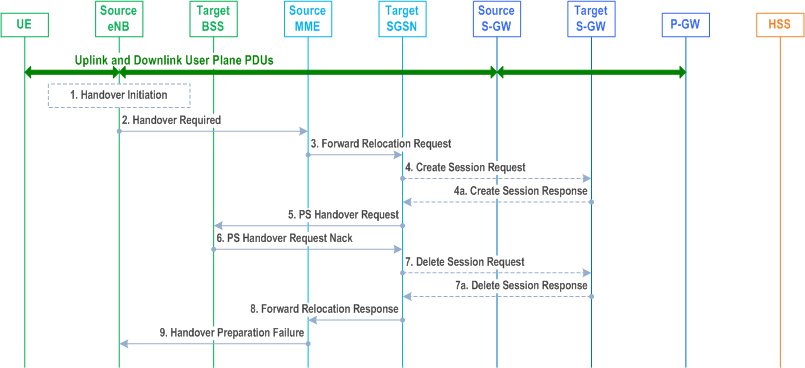
Step 1.
Steps 1 to 5 in the flow are identical to the ones in clause 5.5.2.3.2.
Step 6.
If the Target BSS fails to allocate any resources for any of the requested PFCs it sends a PS Handover Request Nack (Cause) message to the Target SGSN. When the Target SGSN receives the PS Handover Request Nack message from Target BSS the Target SGSN clears any reserved resources for this UE.
Step 7.
This step is only performed for Serving-GW relocation, i.e. if Steps 4/4a have been performed. The Target SGSN deletes the EPS bearer resources by sending Delete Session Request (Cause) messages to the Target Serving-GW. The Target Serving-GW acknowledges with Delete Session Response (Cause) messages.
Step 8.
The Target SGSN sends the Forward Relocation Response (Cause) message to the Source MME.
Step 9.
When the Source MME receives the Forward Relocation Response message it send a Handover Preparation Failure (Cause) message to the Source eNodeB.
![]()
![]()
![]()