Content for TS 23.401 Word version: 18.6.0
1…
4…
4.2.2…
4.3…
4.3.6…
4.3.8…
4.3.12…
4.3.16…
4.3.20…
4.3.25…
4.4…
4.6…
4.7…
5…
5.1.2…
5.3…
5.3.2…
5.3.3…
5.3.3.2
5.3.3.3…
5.3.4…
5.3.4B…
5.3.5…
5.3.8…
5.3.9…
5.4…
5.4.4…
5.5…
5.5.1.2…
5.5.2…
5.5.2.2…
5.5.2.3…
5.5.2.4…
5.6…
5.7.3…
5.7A…
5.10
5.11…
5.19…
D…
D.3…
D.3.4
D.3.5
D.3.6
D.3.7…
D.3.8…
E
F…
J…
K…
L…
M…
D.3.4 3G SGSN to MME combined hard handover and SRNS relocation procedure p. 393
The 3G Gn/Gp SGSN to MME Combined Hard Handover and SRNS Relocation procedure is illustrated in Figure D.3.4-1.
Any steps descriptions that are from TS 23.060 are shown as italic text and remain unmodified. In those step descriptions an MS stands for UE, new SGSN for new MME and GGSN for P-GW.
The procedure between E-UTRAN eNodeB and UE, and between E-UTRAN eNodeB and MME are compliant with the equivalent procedure parts in clause 5.5: Handover.
If emergency bearer services are ongoing for the UE, the MME checks as part of the Tracking Area Update in the execution phase, if the handover is to a restricted area and if so MME releases the non-emergency bearers as specified in clause 5.10.3.
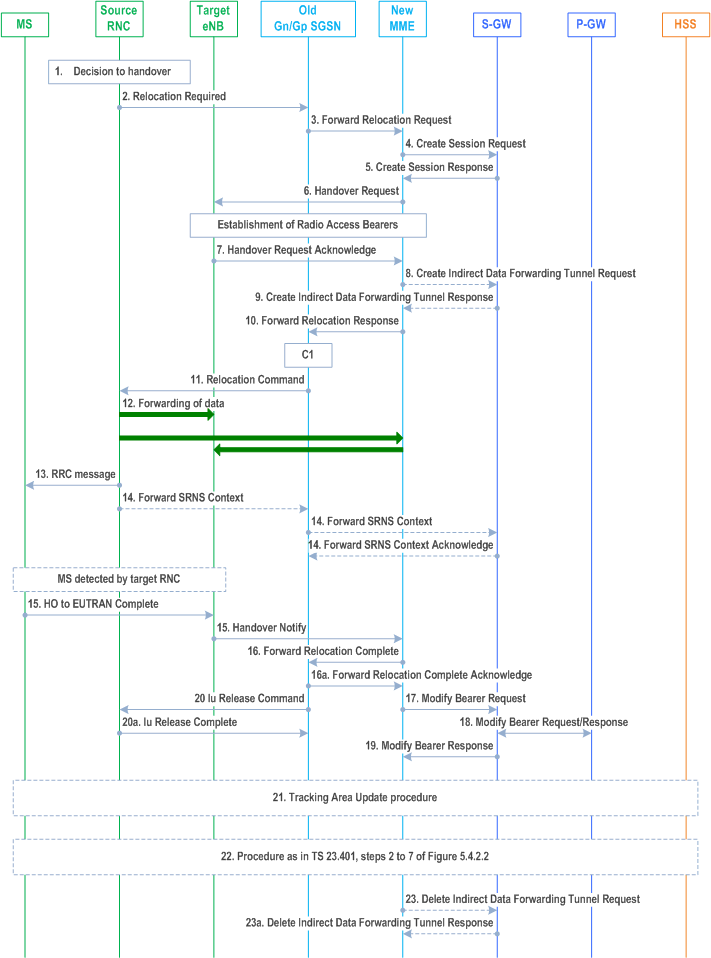
Step 1.
The source RNC decides to initiate a handover to E-UTRAN.
Step 2.
Step 3.
Step 4.
The source SRNC sends a Relocation Required message (Relocation Type, Cause, Source ID, Target ID, Source RNC To Target RNC Transparent Container) to the old SGSN. The source SRNC shall set Relocation Type to "UE Involved". Source RNC To Target RNC Transparent Container includes the necessary information for relocation co-ordination, security functionality and RRC protocol context information (including MS Capabilities).
The old SGSN determines from the Target ID if the SRNS relocation is intra-SGSN SRNS relocation or inter-SGSN SRNS relocation. In the case of inter-SGSN SRNS relocation the old SGSN initiates the relocation resource allocation procedure by sending a Forward Relocation Request message (IMSI, Tunnel Endpoint Identifier Signalling, MM Context, PDP Context, Target Identification, RAN Transparent Container, RANAP Cause, GCSI) to the new SGSN. For relocation to an area where Intra Domain Connection of RAN Nodes to Multiple CN Nodes is used, the old SGSN may - if it provides Intra Domain Connection of RAN Nodes to Multiple CN Nodes -have multiple target SGSNs for each relocation target in a pool area, in which case the old SGSN will select one of them to become the new SGSN, as specified in TS 23.236. PDP context contains GGSN Address for User Plane and Uplink TEID for Data (to this GGSN Address and Uplink TEID for Data, the old SGSN and the new SGSN send uplink packets). At the same time a timer is started on the MM and PDP contexts in the old SGSN (see Routing Area Update procedure in clause "Location Management Procedures (Iu mode)"). The Forward Relocation Request message is applicable only in the case of inter-SGSN SRNS relocation. The old SGSN 'sets' the GCSI flag if the MM context contains GPRS CAMEL Subscription Information.
The MME selects a Serving-GW and sends a Create Session Request (bearer context(s) with PDN-GW addresses and TEIDs for uplink traffic, APN-AMBR, Serving Network, UE Time Zone) message per PDN connection to the target Serving-GW. For relocation from Gn/Gp SGSN, the target MME provides the APN-AMBR if not received explicitly from the Gn/Gp SGSN based on the mapping from MBR (as specified in Annex E) to the Serving-GW.
Step 5.
The Serving-GW allocates the S-GW addresses and TEIDs for the uplink traffic on S1_U reference point (one TEID per bearer). The target Serving-GW sends a Create Session Response (Serving-GW addresses and uplink TEID(s) for user plane) message back to the target MME.
Step 6.
The new MME requests the target eNodeB to establish the bearer(s) by sending the message Handover Request (UE Identifier, S1AP Cause, CN Domain Indicator, KeNB, NAS Security Parameters to E-UTRAN, EPS Bearers to be setup list, Source to Target Transparent Container, Serving-GW Address(es) and TEID(s) for User Traffic Data, Handover Restriction List). S1AP Cause indicates the RANAP Cause as received from SGSN. Source to Target Transparent Container contains the RAN Transparent Container as received from SGSN. The NAS Security Parameters to E-UTRAN includes the NAS Integrity Protection and Ciphering algorithm(s), eKSI and NONCEMME information elements. Handover Restriction List is sent if it is available in the Target MME; it is described in clause 4.3.5.7.
If the MME did not receive the UE Network Capability information from the old SGSN, then the MME will not have received information on the E-UTRAN Integrity Protection and Encryption algorithms that the UE supports. In this case, the MME can assume that the UE supports both EIA1/EEA1 and EIA2/EEA2.
The MME shall not request the target eNodeB to establish EPS GBR bearers with maximum bitrate set to 0 and those EPS bearers should not be included in the EPS Bearers to be setup list and should be deactivated by the MME. For the remaining EPS Bearer Contexts the MME ignores any Activity Status Indicator within an EPS Bearer Context and requests the target eNodeB to allocate resources for all the remaining EPS Bearer Contexts.
The MME shall compute the UE-AMBR, according to clause 4.7.3, based on explicit APN-AMBR values received from the Gn/Gp SGSN. If explicit APN-AMBR values are not received by the MME, a local UE-AMBR shall be included in the 'EPS Bearers be setup list' IE. The local UE-AMBR is described in Annex E.
"Data forwarding not possible" indication per bearer shall be included in the 'EPS Bearers to be setup list' if the target MME decides the corresponding bearer will not be subject to data forwarding.
Step 7.
The target eNodeB allocates the requested resources and returns the applicable parameters to the target MME in the message Handover Request Acknowledge (Target to Source Transparent Container, EPS Bearers setup list, EPS Bearers failed to setup list, Cause). The target eNodeB shall ignore it if the number of radio bearers in the Source to Target Transparent container does not comply with the number of bearers requested by the MME and allocate bearers as requested by the MME.
The target eNodeB inserts the information provided by the MME (KSI, selected NAS Integrity Protection and Ciphering algorithm(s), NONCEMME) and selected AS integrity and ciphering algorithm(s) into the UTRAN RRC message, which is contained in the Target to Source Transparent Container.
Step 8.
If 'Indirect Forwarding' and relocation of Serving-GW apply the target MME sends a Create Indirect Data Forwarding Tunnel Request message (IMSI, MME Tunnel Endpoint Identifier for Control Plane, MME Address for Control plane, Target eNodeB Address and TEID(s) for DL user plane) to the Serving-GW. The allocation of a new Serving-GW by steps 4 and 5 the MME shall consider as a Serving-GW change.
Step 9.
The Serving-GW returns a Create Indirect Data Forwarding Tunnel Response (Cause, Serving-GW DL TEID(s)) message to the source MME. If the Serving-GW doesn't support data forwarding, an appropriate cause value shall be returned.
Step 10.
Step 11.
Step 12.
Step 13.
Step 14.
When resources for the transmission of user data between target RNC and new SGSN have been allocated and the new SGSN is ready for relocation of SRNS, the Forward Relocation Response (Cause, RAN Transparent Container, RANAP Cause, Target-RNC Information) message is sent from the new SGSN to the old SGSN. This message indicates that the target RNC is ready to receive from source SRNC the forwarded downlink PDUs, i.e., the relocation resource allocation procedure is terminated successfully. RAN transparent container and RANAP Cause are information from the target RNC to be forwarded to the source SRNC. The Target RNC Information, one information element for each RAB to be set up, contains the RNC Tunnel Endpoint Identifier and RNC IP address for data forwarding from the source SRNC to the target RNC. The Forward Relocation Response message is applicable only in the case of inter-SGSN SRNS relocation.
For each RAB, if the MME has determined no Data forwarding, i.e. the data forwarding from the source RNC to the target eNodeB is not required, the MME indicates the reserved TEID and IP address parameters to the old SGSN in the Target RNC Information. The packets received on that reserved TEID and IP address are discarded.
The old SGSN continues the relocation of SRNS by sending a Relocation Command message (Target RNC To Source RNC Transparent Container, RABs To Be Released, RABs Subject To Data Forwarding) to the source SRNC. The old SGSN decides the RABs to be subject for data forwarding based on QoS, and those RABs shall be contained in RABs subject to data forwarding. For each RAB subject to data forwarding, the information element shall contain RAB ID, Transport Layer Address, and Iu Transport Association. These are the same Transport Layer Address and Iu Transport Association that the target RNC had sent to new SGSN in Relocation Request Acknowledge message, and these are used for forwarding of downlink N-PDU from the source SRNC to the target RNC. The source SRNC is now ready to forward downlink user data directly to the target RNC over the Iu interface. This forwarding is performed for downlink user data only.
The source SRNC may, according to the QoS profile, begins the forwarding of data for the RABs to be subject for data forwarding.
The data forwarding at SRNS relocation shall be carried out through the Iu interface, meaning that the GTP-PDUs exchanged between the source SRNC and the target RNC are duplicated in the source SRNC and routed at the IP layer towards the target RNC. For each radio bearer which uses lossless PDCP the GTP-PDUs related to transmitted but not yet acknowledged PDCP-PDUs are duplicated and routed at IP layer towards the target RNC together with their related downlink PDCP sequence numbers. The source RNC continues transmitting duplicates of downlink data and receiving uplink data.
Before the serving RNC role is not yet taken over by target RNC and when downlink user plane data starts to arrive to target RNC, the target RNC may buffer or discard arriving downlink GTP-PDUs according to the related QoS profile.
Before sending the RRC message the uplink and downlink data transfer shall be suspended in the source SRNC for RABs, which require delivery order. The RRC message is for example Physical Channel Reconfiguration for RNS to RNS relocation, or Intersystem to UTRAN Handover for BSS to RNS relocation, or Handover from UTRAN Command for BSS relocation, or Handover Command for BSS to BSS relocation. When the source SRNC is ready, the source RNC shall trigger the execution of relocation of SRNS by sending to the MS the RRC message provided in the Target RNC to source RNC transparent container, e.g., a Physical Channel Reconfiguration (UE Information Elements, CN Information Elements) message. UE Information Elements include among others new SRNC identity and S-RNTI. CN Information Elements contain among others Location Area Identification and Routing Area Identification.
When the MS has reconfigured itself, it sends an RRC message e.g., a Physical Channel Reconfiguration Complete message to the target SRNC. If the Forward SRNS Context message with the sequence numbers is received, the exchange of packets with the MS may start. If this message is not yet received, the target RNC may start the packet transfer for all RABs, which do not require maintaining the delivery order.
There is no RAN context transfer during inter RAT handovers with E-UTRAN. If the source RNC originates any SRNC contexts the MME acknowledges the receipt towards the SGSN and ignores the message content.
Step 15.
When the UE has successfully accessed the target eNodeB, the target eNodeB informs the target MME by sending the message Handover Notify (TAI+ECGI). The UE shall implicitly derive the EPS bearers for which an E-RAB was not established from the HO from UTRAN Command and deactivate them locally without an explicit NAS message at this step.
If Dual Connectivity is activated for the UE, the PSCell ID shall be included in the Handover Notify message.
Step 16.
Upon receipt of Handover Notify message, if the SRNS Relocation is an inter SGSN SRNS relocation, the new SGSN signals to the old SGSN the completion of the SRNS relocation procedure by sending a Forward Relocation Complete message.
Upon receipt of the Relocation Complete message the new MME starts a timer.
Step 17.
The target MME will now complete the handover procedure by informing the Serving-GW that the target MME is now responsible for all the bearers the UE have established. This is performed in the message Modify Bearer Request (Cause, Tunnel Endpoint Identifier Control Plane, MME Address for Control Plane, eNodeB Address(es) and TEID(s) for User Traffic, RAT type, APN-AMBR, User Location Information, PSCell ID) per PDN connection. If the PDN-GW requested UE's location information and/or User CSG information (determined from the UE context), the MME also includes the User Location Information IE and/or User CSG Information IE in this message. If the UE Time Zone has changed, the MME includes the UE Time Zone IE in this message. If the MME has received PSCell ID in step 15, the MME shall include it in this message.
The MME releases the non-accepted bearers by triggering the bearer release procedure as specified in clause 5.4.4.2. If the Serving-GW receives a DL packet for a non-accepted bearer, the Serving-GW drops the DL packet and does not send a Downlink Data Notification to the MME.
Step 18.
The Serving-GW informs the PDN-GW the APN-AMBR and the change of for example the RAT type that e.g. can be used for charging, by sending the message Modify Bearer Request (APN-AMBR, Serving Network, PDN Charging Pause Support Indication) per PDN connection. The S-GW also includes User Location Information IE and/or UE Time Zone IE and/or User CSG Information IE if it is present in step 17. The Serving-GW allocates DL TEIDs on S5/S8 even for non-accepted bearers. The PDN-GW must acknowledge the request with the message Modify Bearer Response (Default bearer id, APN Restriction, PDN Charging Pause Enabled Indication (if PDN-GW has chosen to enable the function)). When the UE moves from Gn/Gp SGSN to the MME, the PDN-GW shall send the APN restriction of each bearer context to the Serving-GW.
Step 19.
The Serving-GW acknowledges the user plane switch to the target MME via the message Modify Bearer Response (Cause, Tunnel Endpoint Identifier Control Plane, Serving-GW Address for Control Plane, Default bearer id, APN restriction). The Serving-GW shall forward the received APN Restriction to the MME. At this stage the user plane path is established for all bearers between the UE, target eNodeB, Serving-GW and PDN-GW.
Step 20.
Step 21.
Upon receiving the Relocation Complete message or, if it is an inter-SGSN SRNS relocation, the Forward Relocation Complete message, the old SGSN sends an Iu Release Command message to the source RNC. When the RNC data-forwarding timer has expired, the source RNC responds with an Iu Release Complete message.
The UE initiates a Tracking Area Update procedure when one of the conditions listed in clause "Triggers for tracking area update" applies.
The target MME knows that an IRAT Handover has been performed for this UE as it received the bearer context(s) by handover messages and therefore the target MME performs only a subset of the TA update procedure, specifically it excludes the context transfer procedures between source SGSN and target MME. The target MME gets the subscribed UE-AMBR value and the subscribed APN-AMBR value from the HSS during the TA update procedure.
If the Subscription Data received from the HSS (during the TAU) contains information that is necessary for the E-UTRAN to be aware of (e.g. a restriction in the UE's permission to use NR as a secondary RAT, Unlicensed Spectrum in the form of LAA/LWA/LWIP/NR-U (as specified in clause 4.3.30) or a combination of them), or an existing UE context in the MME indicates that the UE is not permitted to use NR as a secondary RAT, Unlicensed Spectrum or a combination of them, and the MME has not provided this information to the target eNodeB during step 6 (the Handover Request), then the MME sends an updated Handover Restriction List in the Downlink NAS Transport message that it sends to E-UTRAN.
Step 22.
The target MME calculates UE-AMBR as defined in clause 4.7.3. If this calculated value is different from the UE-AMBR computed during step 6, or the APN-AMBR mapped from the subscribed MBR is different from the subscribed APN-AMBR, or the mapped subscribed QoS profile (i.e. the subscribed QoS profile mapped according to Annex E) of the default bearer is different from the EPS Subscribed QoS profile received from the HSS, the new MME shall initiate Subscribed QoS Modification procedure as described in clause 5.4.2.2, Figure 5.4.2.2-1.
Step 23.
When the timer started in step 16 expires the new MME releases the resources that have been allocated for indirect forwarding.
If the SRNS Relocation is inter-SGSN, then the following CAMEL procedure calls shall be performed (see referenced procedures in TS 23.078)
C1)
The new SGSN shall determine the Maximum APN restriction based on the received APN Restriction of each PDP context from the GGSN and then store the new Maximum APN restriction value.
If the SRNS Relocation is intra-SGSN, then the above mentioned CAMEL procedures calls shall not be performed.
If Routing Area Update occurs, the SGSN shall determine whether Direct Tunnel can be used based on the received GPRS CAMEL Subscription Information. If Direct Tunnel can not be maintained the SGSN shall re-establish RABs and initiate the Update PDP Context procedure to update the IP Address and TEID for Uplink and Downlink data.
If Routing Area Update occurs, then the following CAMEL procedure calls shall be performed (see referenced procedures in TS 23.078):
CAMEL_GPRS_PDP_Context_Disconnection, CAMEL_GPRS_Detach and CAMEL_PS_Notification.
They are called in the following order:
- The CAMEL_GPRS_PDP_Context_Disconnection procedure is called several times: once per PDP context. The procedure returns as result "Continue".
- Then the CAMEL_GPRS_Detach procedure is called once. The procedure returns as result "Continue".
- Then the CAMEL_PS_Notification procedure is called once. The procedure returns as result "Continue".
![]()
![]()
![]()