Content for TS 23.247 Word version: 18.6.0
1…
4…
4.2…
4.3
5…
6…
6.6…
7…
7.1.1.2
7.1.1.3
7.1.1.4…
7.1.1.6…
7.1.2…
7.2…
7.2.2…
7.2.3…
7.2.4…
7.2.4.3…
7.2.5…
7.2.6…
7.3…
7.3.5…
7.5…
8…
9…
9.2…
9.3…
9.4…
A…
7.2.3 Mobility Procedures for MBS
7.2.3.1 General
7.2.3.2 Xn based handover from MBS supporting NG-RAN node
7.2.3.3 N2 based handover from MBS supporting NG-RAN node
7.2.3.4 Xn/N2 based handover from non-MBS supporting NG-RAN node
7.2.3.5 Minimization of data loss
7.2.3.6 Xn/N2 based handover for inactive MBS session
7.2.3.7 Connection Resume in RRC_INACTIVE procedure
7.2.3.8 Mobility procedures to enable delivery of multicast MBS session data to UEs in RRC_INACTIVE state
7.2.3.8.1 General
7.2.3.8.2 Mobility of UE in RRC_INACTIVE state receiving MBS data within RNA
7.2.3.8.3 Mobility of UE in RRC_INACTIVE state receiving MBS data out of RNA and within RA
7.2.3.8.4 Mobility of UE in RRC_INACTIVE state receiving MBS data out of RA
...
...
7.2.3 Mobility Procedures for MBS p. 73
7.2.3.1 General p. 73
UE may move from one NG-RAN node to another NG-RAN node after UE has joined the MB Session. There are various mobility scenarios possible, depending on whether one of the involved NG-RAN nodes supports MBS.
During an active MBS Session, mobility between an NG-RAN supporting MBS and an NG-RAN node not supporting MBS requires the mobility procedure to provide the appropriate MBS traffic delivery method at the target NG-RAN node.
7.2.3.2 Xn based handover from MBS supporting NG-RAN node p. 73
This clause describes an Xn based handover with MBS traffic delivered to the UE at the source NG-RAN node supporting MBS.
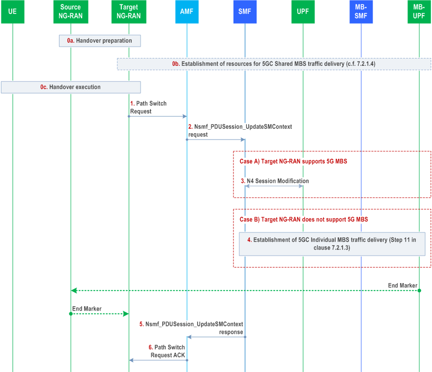
The following additions apply compared to clause 4.9.1.2 of TS 23.502:
Before Handover:
The source NG RAN has been provided with MBS Session Resource information (including the MBS Session ID and multicast QoS flow information) and the UE Context information contains a mapping information within the PDU Session Resource associated with the MBS Session Resource, e.g. including mapped unicast QoS Flows associated with the multicast QoS flow(s) of the MBS Session Resource.
Handover Preparation Phase:
At Xn handover, the target NG-RAN is provided with MBS session information by the source NG-RAN which causes:
- an MBS non-supporting target NG-RAN node to prepare the unicast resources according to associated QoS flow(s) information.
- an MBS supporting target NG-RAN node to allocate to the UE shared NG-RAN resources according to the MBS session information. If the 5GC Shared MBS traffic delivery for the indicated multicast MBS Session has not been established in target NG-RAN, target NG-RAN triggers setup of the resources for the 5GC Shared MBS traffic delivery, see clause 7.2.1.4 for details.
Step 1.
The SMF differentiates two cases:
Case A) The target NG-RAN supports MBS. Step 3 applies and step 4 is skipped.
Target NG-RAN to AMF: the target NG-RAN sends N2 Path Switch Request to AMF.
The target NG-RAN node, if MBS-capable, indicates it supports of MBS to SMF in N2 SM information. Per the received N2 SM information, the SMF knows whether the target NG-RAN node supports MBS and determines the delivery method, i.e. whether the 5GC Shared MBS traffic delivery or 5GC Individual MBS traffic delivery is used for MBS data transferring.
Step 3.
Case B) The target NG-RAN does not support MBS. Step 3 is skipped, step 4 applies.
SMF to UPF: The SMF invokes N4 Session Modification procedure with the UPF (PSA) only for unicast PDU Session.
Step 4.
This step is the same as described in step 11 of clause 7.2.1.3.
The details of how to perform data forwarding refers to clause 7.2.3.5.
Step 5.
SMF to AMF: The SMF responds to AMF through Nsmf_PDUSession_UpdateSMContext response.
Step 6.
AMF to target NG-RAN: The AMF sends the path switch Ack to target NG-RAN.
7.2.3.3 N2 based handover from MBS supporting NG-RAN node p. 75
This clause describes the N2 based handover with MBS traffic delivered to the UE at the source NG-RAN node supporting MBS.
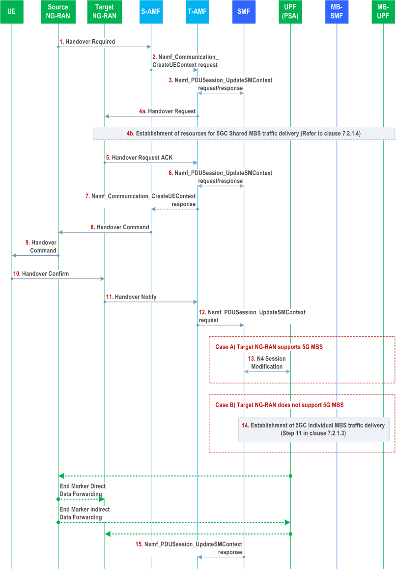
The following additions apply compared to clause 4.9.1.3 of TS 23.502):
Step 1.
Source NG-RAN to S-AMF: Handover Required (RAN container (MBS Session information, associated PDU session information, [associated QoS flow information and corresponding multicast QoS flow information])).
Step 2.
[Conditional] S-AMF to T-AMF: The T-AMF is provided with associated PDU Session information and the MBS session related information.
Step 3.
T-AMF and SMF(s): T-AMF interacts with SMF via Nsmf_PDUSession_UpdateSMContext request/response. In the response sent by SMF, multicast MBS session related information (i.e. MBS session ID and optionally the mapping between the multicast QoS flow(s) and associated QoS flow(s)), is included in the N2 SM information.
Step 4.
T-AMF to Target NG-RAN: The Target NG-RAN prepares the radio resource based on the received information:
Step 5.
- If the Target NG-RAN does not support MBS, the MBS Session related information is not used. The Target NG-RAN uses the associated PDU Session information to allocate resource to deliver MBS data. The MBS data are transmitted via the associated QoS flows within the associated PDU Session.
- If the Target NG-RAN supports MBS, the Target NG-RAN uses the multicast MBS Session related information to allocate RAN resources to deliver the MBS data. If 5GC Shared MBS traffic delivery for the indicated multicast MBS session has not been established towards the Target NG-RAN, the Target NG-RAN initiates the shared delivery establishment towards the MB-SMF via AMF as described in clause 7.2.1.4.
Target NG-RAN to T-AMF: The target NG-RAN sends Handover Request Ack to T-AMF.
The target NG-RAN node, if MBS-capable, indicates it supports MBS to SMF in N2 SM information. Per the received N2 SM information, the SMF knows whether the target NG-RAN node supports MBS and determines the delivery method, i.e. whether the 5GC Shared MBS traffic delivery or 5GC Individual MBS traffic delivery is used for MBS data transferring.
Step 12.
T-AMF to SMF: The AMF invokes Nsmf_PDUSession_UpdateSMContext request towards SMF, the message includes the received N2 SM information received from the target NG-RAN.
Step 13-14.
Same as described in steps 3-4 of clause 7.2.3.2.
The details of how to perform data forwarding, refers to clause 7.2.3.5.
Step 15.
SMF to T-AMF: The SMF sends the Nsmf_PDUSession_UpdateSMContext Response to the T-AMF.
7.2.3.4 Xn/N2 based handover from non-MBS supporting NG-RAN node p. 76
When the UE has joined the multicast MBS session and the source NG-RAN node does not support MBS, the 5GC Individual MBS traffic delivery method is used for the multicast MBS session data delivery. When the Xn/N2 based handover procedure is triggered, the UE is handed over to the target NG-RAN node per existing Xn /N2 based handover procedure defined in TS 23.502.
The following applies for an Xn based handover from an NG-RAN node not supporting 5G MBS:
- The source NG-RAN node requests the associated QoS Flow(s) in the associated PDU session to be handed over to the target NG-RAN node.
- In the Path Switch Request message, the target NG-RAN node, if MBS-capable, indicates it supports MBS to the SMF in the N2 SM information.
- After successful handover, if the target NG-RAN node supports MBS, the SMF triggers modification of the associated PDU Session at the target NG-RAN node by including the multicast MBS session related information in N2 SM Information as described in step 7 of clause 7.2.1.3, which may trigger the target NG-RAN node to initiate establishment of shared delivery as described in clause 7.2.1.4. NG-RAN provides the response to the request for the modification of the PDU session when the shared delivery of the MBS session data to the related UE (if applicable) is available
- Based on the response of PDU session modification procedure, the SMF changes the MBS session data delivery method from 5GC Individual MBS traffic delivery method to 5GC shared MBS traffic delivery method, and sends N4 Session modification message to UPF to configure UPF to not forward the received multicast MBS session data via the associated PDU Session. If there are no multicast MBS session data forwarding via the associated PDU session(s) needed, the SMF may also release the shared tunnel between the UPF and MB-UPF.
- During handover preparation phase, the SMF includes the multicast MBS session related information in N2 SM Information as described in step 7 of clause 7.2.1.3 and sends it to the target NG-RAN. The target NG-RAN, if MBS-capable, indicates it supports MBS to SMF in N2 SM information. If the target NG-RAN node supports MBS, the target NG-RAN node adds the UE into the MBS Session Context. If 5GC Shared MBS traffic delivery for the indicated multicast MBS session has not been established towards the target NG-RAN, the target NG-RAN uses the multicast MBS Session related information to allocate RAN resources to deliver the MBS data and initiates the shared delivery establishment towards the MB-SMF as described in clause 7.2.1.4.
- Based on the received MBS support information in N2 SM information from the target NG-RAN, the SMF determines the MBS data delivery method for the multicast MBS session. The SMF configures UPF to not forward the received multicast service data to the associated PDU Session via N4 Session modification message, i.e. SMF changes 5GC individual MBS traffic delivery to 5GC shared MBS traffic delivery. If there are no multicast MBS session data forwarding via the associated PDU session(s), the SMF may also release the shared tunnel between the UPF and MB-UPF.
7.2.3.5 Minimization of data loss p. 77
To minimize data loss of a multicast MBS session during the handover procedure the following functions apply:
- For each MBS QoS flow, the MB-UPF adds a sequence number in each data packet of the MBS session sent by the MB-UPF and forwarded to all related NG-RAN nodes and UPFs via GTP-U tunnel. When the UPF forwards the received MBS data packet, the sequence number shall not be changed.
-
If both the source NG-RAN node and target NG-RAN node support MBS, to minimize data loss of the MBS session either of, or a combination of, the following methods may be applied, as specified in TS 38.300:
- Data may be forwarded from source NG-RAN node to target NG-RAN node. In handover preparation phase, the MBS progress information (i.e. PDCP number) is exchanged between source NG-RAN node and target NG-RAN node.
- NG-RAN nodes share a common user plane entity, denoted as shared NG-U termination in TS 38.300, which allows the allocation of identical PDCP numbers to MBS users data when delivered to UEs in cells served by different NG-RAN nodes.
- If source NG-RAN node supports MBS and target NG-RAN node does not support MBS, the multicast MBS session data is forwarded from source NG-RAN node to target NG-RAN node via data forwarding tunnels allocated by the target NG-RAN node associated with the mapped unicast QoS flows within the associated PDU session according to the data forwarding mechanism defined in TS 23.502.
- If source NG-RAN node does not support MBS and target NG-RAN node supports MBS, for Xn/N2 handover, the multicast MBS session data is forwarded to the target NG-RAN node as the data forwarding mechanism defined in TS 23.502. Directly after the handover the target NG-RAN node thus still receives MBS session data via individual delivery. The UPF forwards multicast MBS session data within the associated PDU session which includes the sequence number received from the MB-UPF to the target NG-RAN node. Shared delivery of MBS data towards the target RAN node is being established as described in clause 7.2.1.4 and the target RAN node receives sequence numbers as part of the MBS data with sequence numbers via shared delivery.
7.2.3.6 Xn/N2 based handover for inactive MBS session p. 77
If the MBS session is in Inactive state, the following differences apply as compared to the handover procedures for the MBS session in Active state:
- The target NG-RAN is provided with the MBS session ID, but is not provided with Active MBS Session Information by the source NG-RAN as specified in TS 38.423 and in TS 38.413.
- For Xn/N2 based handover, the information that MBS session is Inactive state is implied by the lack of Active MBS Session Information provided from the source RAN node towards the target RAN node.
- For the MBS supporting NG-RAN node, the target NG-RAN establishes the shared tunnel with the MB-UPF as usual, if it hasn't been established before. However, as the MBS session is in Inactive state, the NG-RAN node will not allocate related radio resource.
- After a handover to a target NG-RAN node not supporting MBS, the SMF removes the associated QoS flow(s) information.
7.2.3.7 Connection Resume in RRC_INACTIVE procedure p. 78
If an MBS session is in Inactive state, the UE may be in CM-CONNECTED with RRC_INACTIVE state. If an MBS Session is in Active state, the UE may also be in CM-CONNECTED with RRC_INACTIVE state as specified in clause 16.10.5.2 of TS 38.300.
The UE may resume the connection in a different NG-RAN node as specified in clauses 4.8.2.2 and 4.8.2.2a of TS 23.502, with following enhancement when the context retrieval is successful:
-
For an MBS supporting NG-RAN:
- if the UE context retrieved from the last serving NG-RAN includes MBS session information and the NG-RAN node has not yet established the 5GC Shared MBS traffic delivery for the MBS session, the NG-RAN establishes the 5GC Shared MBS traffic delivery as specified in clause 7.2.1.4. The NG-RAN then sends Path Switch Request indicating the MBS support information;
- if the UE context retrieved from the last serving NG-RAN does not include MBS session information, Path Switch Request sent from NG-RAN includes the MBS support information. Based on the MBS support information, the SMF, after acknowledging the path switch request, provides the MBS related information and if applicable the associated QoS flow(s) information to the NG-RAN as specified in clause 7.2.1.3. The NG-RAN establishes the 5GC Shared MBS traffic delivery as specified in clause 7.2.1.4.
- For an MBS non-supporting NG-RAN, Path Switch Request sent from NG-RAN does not include the MBS support information. If the MBS session is still inactive, the SMF, after acknowledging the path switch request, removes the associated QoS flow(s) information if it was provided before.
7.2.3.8 Mobility procedures to enable delivery of multicast MBS session data to UEs in RRC_INACTIVE state |R18| p. 78
7.2.3.8.1 General p. 78
The procedures in clauses 7.2.3.2, 7.2.3.3, 7.2.3.4, 7.2.3.6 and 7.2.3.7 apply with the following additions:
- During Xn handover, if the target NG-RAN node support MBS multicast with reception in RRC_INACTIVE state, it indicates to the SMF in the N2 SM information in the Path Switch Request message that it supports MBS multicast with reception in RRC_INACTIVE state.
- During N2 handover, if the target NG-RAN node support MBS multicast with reception in RRC_INACTIVE state, it indicates to the SMF in the N2 SM information in the Handover Request Ack message that it supports MBS multicast with reception in RRC_INACTIVE state.
-
If the MBS assistance information is available at the SMF for an MBS session that the UE joined:
- If the MBS assistance information is available at the SMF for an MBS session that the UE joined,
- If there is signalling of MBS session related information from SMF to target RAN node, the SMF includes MBS Assistance Information in the N2 SM information.
- For N2-based handover, when the SMF provides the MBS session related information as part of the associated PDU Session context data as specified in the existing procedures, the SMF also includes the MBS Assistance Information in the N2 SM information.
- For Xn-based handover or Connection Resume towards an target RAN node that supports MBS multicast with reception in RRC_INACTIVE state, if the source RAN does not support MBS multicast with reception in RRC_INACTIVE state, after successful handover the SMF triggers a modification of the associated PDU Session and provides the MBS Assistance Information in N2 SM Information.
- For Xn-based handover or Connection Resume, the MBS session information transferred from source NG-RAN towards target NG-RAN also include MBS assistance information for the MBS session if such information is available at the source RAN node as specified in TS 38.300.
- UE moves to new cell within the RAN Notification Area (RNA).
- UE moves outside the current RAN Notification Area but within the current Registration Area (RA).
- UE moves out of the current Registration Area.
7.2.3.8.2 Mobility of UE in RRC_INACTIVE state receiving MBS data within RNA p. 79
When a UE in RRC_INACTIVE state is receiving ongoing MBS session data and moves to a new cell within the RNA, the UE may receive the MBS session data in RRC_INACTIVE state or resume the connection as specified in TS 38.300.
7.2.3.8.3 Mobility of UE in RRC_INACTIVE state receiving MBS data out of RNA and within RA p. 79
When a UE in RRC_INACTIVE state is receiving multicast MBS session data, if the UE moves out of the RNA and within the RA, the UE resumes the connection in the same way as specified in clause 7.2.3.7.
7.2.3.8.4 Mobility of UE in RRC_INACTIVE state receiving MBS data out of RA p. 79
When the UE in RRC_INACTIVE receiving multicast MBS session data, if the UE moves out of the RA, the UE initiates the Mobility Registration Update procedure to activate the associated PDU session(s) as specified in clause 4.2.2.2.2 of TS 23.502. Hence the shared delivery (if not already established) or the individual delivery can be established towards the NG-RAN node to enable delivery of multicast MBS session data to the UEs.
![]()
![]()
![]()