Content for TS 33.127 Word version: 18.7.0
0…
5…
5.4…
5.6…
5.7…
6…
6.2.2…
6.2.3…
6.2.5…
6.3…
6.3.3…
6.3.4…
6.4…
7…
7.3…
7.4…
7.4.7…
7.5…
7.6…
7.7…
7.8…
7.9…
7.10…
7.11…
7.12…
7.13…
7.14…
7.15…
7.16…
8…
A…
A.2…
A.3…
A.4…
B…
D…
E…
6.3.3 LI at SGW/PGW
6.3.3.1 Architecture
6.3.3.1.1 General
6.3.3.1.2 Non-CUPS architecture
6.3.3.1.3 EPS CUPS Architecture
6.3.3.2 Target identities
6.3.3.3 IRI events
6.3.3.3.1 Option A
6.3.3.3.1.1 General
6.3.3.3.1.2 xIRI records for architectures with EPC/5GC interworking
6.3.3.3.2 Option B
6.3.3.4 Common IRI parameters
6.3.3.5 Specific IRI parameters
6.3.3.6 Network topologies
6.3.3.6.1 Network topologies without EPC/5GC interworking
6.3.3.6.2 Network topologies with EPC/5GC interworking
6.3.3.7 EPC-5GC Interworking via SMF+PGW-C and UPF+PGW-U
...
...
6.3.3 LI at SGW/PGW p. 64
6.3.3.1 Architecture p. 64
6.3.3.1.1 General p. 64
In the EPC network, the SGW is the gateway which terminates the user plane interface as specified in TS 23.401. The PGW is the gateway which terminates the SGi interface towards the PDN as specified in TS 23.401. Additionally, the PGW is the user plane anchor for mobility between 3GPP access and non-3GPP access as specified in TS 23.402.
The SGW and PGW shall include an IRI-POI that has the LI capabilities to generate the target UE's bearer related and a CC-POI that has the LI capabilities to duplicate the user plane packets from the EPS bearers related to a target UE.
As defined in TS 23.214, the SGW and PGW may have separated control plane and user plane functions (CUPS). The control plane (CP) functions (SGW-C and PGW-C) provide the traffic forwarding rules (referred to as Forward Action Rules in TS 23.214) to the user plane (UP) functions (SGW-U and PGW-U). The UP functions forward the user plane traffic as per the Forward Action Rules.
In the following clauses, EPS architecture that does not separate the control plane and user plane functions of the SGW/PGW is referred to as non-CUPS EPS.
The LI architecture for non-CUPS EPS is defined in clause 6.3.3.1.2. For non-CUPS EPS architecture, the SGW and PGW function as both CP Entities and the UP Entities.
The LI architecture for CUPS EPS is defined in clause 6.3.3.1.3. For CUPS EPS architecture:
- The CP Entities are the SGW-C and the PGW-C.
- The UP Entities are the SGW-U and the PGW-U.
-
The LI functions present in the SGW-C/PGW-C are:
- The IRI-POI.
- The IRI-TF.
- The CC-TF.
-
The LI functions present in the SGW-U/PGW-U are:
- The CC-POI.
- The IRI-POI.
-
The LI functions present in the SMF+PGW-C are:
- The IRI-POI.
- The CC-TF.
- The IRI-TF.
-
The LI functions present in the UPF+PGW-U are:
- The CC-POI.
- The IRI-POI.
6.3.3.1.2 Non-CUPS architecture p. 65
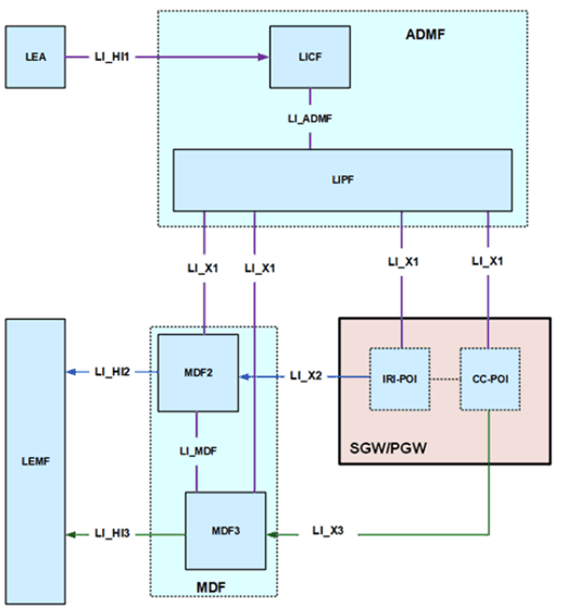
Figure 6.3-2 shows the LI architecture for non-CUPS SGW/PGW based interception.

The LICF present in the ADMF receives the warrant from an LEA, derives the intercept information from the warrant and provides the same to the LIPF.
The LIPF present in the ADMF provisions IRI-POI present in the SGW/PGW, MDF2 and MDF3 over the LI_X1 interfaces. To enable the interception of the target's user plane packets (e.g. when the warrant requires the interception of communication contents), the CC-POI present in the SGW/PGW is also provisioned with the intercept data.
The IRI-POI present in the SGW/PGW detects the target UE's bearer activation, modification and deactivation, generates and delivers the xIRI to the MDF2 over LI_X2. The MDF2 delivers the IRI messages to the LEMF over LI_HI2.
The CC-POI present in the SGW/PGW generates the xCC from the user plane packets and delivers the xCC (that includes the correlation number and the target identity) to the MDF3. The MDF3 delivers the CC to the LEMF over LI_HI3.
A warrant that does not require the interception of communication contents, may require IRI messages that have to be derived from the user plane packets. To support the generation of related xIRI (i.e. that requires access to the user plane packets), the present document supports two implementation approaches described in clause 7.12.2
6.3.3.1.3 EPS CUPS Architecture p. 66
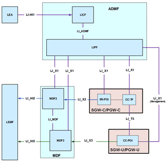
Figure 6.3-3 shows the LI architecture for EPS CUPS SGW/PGW based interception.

The LICF present in the ADMF receives the warrant from an LEA, derives the intercept information from the warrant and provides the same to the LIPF.
The LIPF present in the ADMF provisions IRI-POI present in the SGW-C/PGW-C and the MDF2 over the LI_X1 interfaces. To enable the interception of the target's user plane packets (e.g. when the warrant requires the interception of communication contents), the CC-TF present in the SGW-C/PGW-C is also provisioned with the intercept data.
When PGW-C and PGW-U (represented in Figure 6.3-3) are part of combined SMF+PGW-C and UPF+PGW-U respectively in the EPC-5GC interworking architectures as shown in clause A.2.2, Figure A.2-1 of the present document, the SMF+PGW-C and UPF+PGW-U shall exhibit the LI functions as described in clause 6.3.3.3.1.
The IRI-POI present in the SGW-C/PGW-C detects the target UE's bearer activation, modification and deactivation and generates and delivers the xIRI to the MDF2 over LI_X2. The MDF2 delivers the IRI messages to the LEMF over LI_HI2.
The CC-TF present in the SGW-C/PGW-C detects the target UE's bearer activation, modification and deactivation and provisions the CC-POI in the SGW-U/PGW-U.
The CC-POI present in the SGW-U/PGW-U generates the xCC from the user plane packets and delivers the xCC (that includes the correlation number and the target identity) to the MDF3. The MDF3 delivers the CC to the LEMF over LI_HI3.
A warrant that does not require the interception of communication contents, may require IRI messages that have to be derived from the user plane packets. To support the generation of related xIRI (i.e. that requires access to the user plane packets), the present document supports two implementation approaches described in clause 7.12.2.
6.3.3.2 Target identities p. 68
The LI functions in the SGW/PGW shall support the following target identities for provisioning:
- IMSI.
- MSISDN.
- IMEI.
- SUPI.
- IMSI.
- GPSI.
- MSISDN.
- PEI.
- IMEI.
6.3.3.3 IRI events p. 68
6.3.3.3.1 Option A p. 68
6.3.3.3.1.1 General p. 68
When Option A described in clause 6.3.1 is used, xIRI provided by the IRI-POI in the SMF+PGW-C based on the events specified in TS 33.107 shall not be generated; the IRI-POI in the SMF+PGW-C shall generate xIRI when it detects the following specific events or information specified in TS 33.128:
- PDN connection establishment.
- PDN connection modification.
- PDN connection release.
- Start of interception with an established PDN connection.
- Unsuccessful procedure.
6.3.3.3.1.2 xIRI records for architectures with EPC/5GC interworking p. 69
For the interception of home routed roaming sessions in the visited network, the POIs and TFs shall be present in the SGW and the SMF in the VPLMN and the xIRI records described in the present clause and clause 6.2.3.3 shall be generated.
For all other cases, the POIs and TFs shall be present in the SMF+PGW-C and SMF+PGW-U as described in clause 6.3.3.6.2 and the following events shall be generated.
The PDU session establishment xIRI is generated when the IRI-POI present in the SMF+PGW-C detects that a PDU session with mapped EBIs has been established for the target UE or that a PDN connection has been established for the target UE.
The PDU session modification xIRI is generated when the IRI-POI present in the SMF+PGW-C detects that a PDU session or EBIs are modified for the target UE or when a target UE's PDN connection from EPC is migrated to the 5GS or when a dedicated EPS bearer is activated or deactivated for the target UE.
The PDU session release xIRI is generated when the IRI-POI present in the SMF+PGW-C detects that a PDU session is released or when the default EBI for a PDN connection is deactivated for the target UE.
The start of interception with an established PDU Session xIRI is generated when the IRI-POI present in a SMF+PGW-C detects that interception is activated on the target UE that has an already established PDU session in the 5GS that has a mapped to PDN connection or an already established PDN connection in EPS. When a target UE has multiple 5GC PDU sessions mapped to multiple PDN connections in EPC or when a target UE has multiple PDN connections in EPC, this xIRI shall be sent for each PDU session and each PDN connection with different correlation information values.
When xIRIs are generated due to the detection of a PDU session with mapped EBIs, no separate xIRIs shall be generated for the same events for the corresponding PDN connection.
When additional warrants are activated on a target UE, MDF2 shall be able to generate and deliver the start of interception with an established PDU session related IRI messages to the LEMF associated with the warrants without receiving the corresponding start of interception with an established PDU session xIRI.
When the warrant requires the packet header information reporting, the following xIRI shall be generated:
- Packet header information report (see clause 7.12.2).
6.3.3.3.2 Option B p. 69
The IRI-POI present in the SGW/PGW shall generate xIRI, when it detects the applicable events specified in TS 33.107.
6.3.3.4 Common IRI parameters p. 69
The list of xIRI parameters is specified in TS 33.128. All xIRI shall include the following:
- Target identity.
- Time stamp.
- Correlation information.
- Location information.
- Session related information.
6.3.3.5 Specific IRI parameters p. 69
The parameters in each xIRI are defined in TS 33.128.
6.3.3.6 Network topologies p. 70
6.3.3.6.1 Network topologies without EPC/5GC interworking p. 70
The SGW shall provide the IRI-POI and CC-POI functions (and the IRI-TF and CC-TF in CUPS architecture) in the following network topology cases:
- Based on the deployment option, in a non-roaming case for E-UTRAN.
- Home Routed Roaming case, in VPLMN.
- Based on the deployment option, Local Breakout Roaming case in VPLMN.
- Based on the deployment option, in a non-roaming case for E-UTRAN.
- Home Routed Roaming case, in HPLMN.
- Non-3GPP access case, in the HPLMN.
- Based on the deployment option, Local Breakout Roaming case in VPLMN.
6.3.3.6.2 Network topologies with EPC/5GC interworking p. 70
The SMF+PGW-C shall provide the IRI-POI, the IRI-TF and the CC-TF and the UPF+PGW-U shall provide the IRI-POI and CC-POI in the following network topology cases:
- In the non-roaming case.
- Roaming with local breakout case, in VPLMN.
- Home Routed Roaming case, in HPLMN.
- Non-3GPP access case, in the HPLMN.
- Local Breakout Roaming with Non-3GPP access case, in the VPLMN.
- Home Routed Roaming case, in the VPLMN.
6.3.3.7 EPC-5GC Interworking via SMF+PGW-C and UPF+PGW-U p. 70
In the case of interworking between EPC and 5GC via combined nodes (e.g. SMF+PGW-C, UPF+PGW-U) as defined in clause 5.17 of TS 23.501, all of the requirements found in clause 6.2.3 (LI for SMF/UPF) and clause 6.3.3 (LI at the SGW/PGW) of the present document apply with the following modifications:
- PDN Connection context information present in the combined SMF+PGW-C shall be reported via the mechanisms defined in clause 6.2.3 of TS 33.128.
- User identifiers that are EPC specific but known in the combined SMF+PGW-C are reported as supplemental user IDs per clause 6.2.3 of TS 33.128.