Content for TS 33.127 Word version: 18.7.0
0…
5…
5.4…
5.6…
5.7…
6…
6.2.2…
6.2.3…
6.2.5…
6.3…
6.3.3…
6.3.4…
6.4…
7…
7.3…
7.4…
7.4.7…
7.5…
7.6…
7.7…
7.8…
7.9…
7.10…
7.11…
7.12…
7.13…
7.14…
7.15…
7.16…
8…
A…
A.2…
A.3…
A.4…
B…
D…
E…
8 LI security and deployment considerations
8.1 Introduction
8.2 Architectural alternatives
8.2.1 Full target list at every POI node
8.2.2 Full target list only in LICF
8.2.3 Provisioning for registered users
8.3 LI key management at ADMF
8.3.1 General
8.3.2 Key management
8.4 Virtualised LI security
8.4.1 General
8.4.2 NFVI and host requirements
8.4.3 Virtualised LI function implementation
8.4.4 Container based deployments
8.5 Points of Interception
8.6 Deployment considerations
8.6.1 General
8.6.2 CC-PAG
...
...
8 LI security and deployment considerations p. 148
8.1 Introduction p. 148
The most sensitive information in the LI system is the target list. This is the list of all the subjects in the network currently under surveillance, whether active, suspended or in any other state. The security measures used by the carrier to prevent unauthorized access to this list is not subject to standardization, but the architectural choices made in the design of the LI system do impact the security of the target list directly.
Since completeness of the interception product is a legal requirement in most jurisdictions, the LI system shall ensure that no events that are lawfully authorized for interception are missed (or collected in error). To ensure that no events are missed there are two architectural alternatives.
8.2 Architectural alternatives p. 148
8.2.1 Full target list at every POI node p. 148
A carrier may choose to deploy the full target list at all POIs, such that when a UE arrives in the network and commences registration, the POI is fully armed and in position to recognize if the target identifier is in the target list. The choice to push the full list to every node is the simplest, and arguably the riskiest, since the compromise of any node will leak the complete target list.
8.2.2 Full target list only in LICF p. 148
A Communication Service Provider (CSP) may choose to selectively distribute specific target identifiers to specific POIs, rather than distributing the full target list to all POIs. This choice introduces a race condition. When the UE appears, the POI shall query the ADMF/LICF to find out if the user identifier is part of the target list. As the registration sequence progresses, the NF POI is waiting for a response from the ADMF/LICF. When the reply arrives, the POI can take action if the reply is positive. If the reply is negative, the POI's involvement ends.
If the reply is positive, depending on how long the POI-(ADMF/LICF)-POI round trip for the query/reply took, it is possible that some reportable events are missed. To mitigate this there are two further alternatives:
- the carrier may choose to delay completion of the registration for all users for the time it takes the ADMF/LICF to answer, thus inducing a registration delay in all registrations, whether the user is a target or not, or
- the carrier may choose to cache the reportable registration events while the POI-(ADMF/LICF)-POI query is running, and either report them if the answer is positive, or delete them if the answer is negative.
8.2.3 Provisioning for registered users p. 149
When a new target is provisioned in the LI system, after the target is already registered in the CSP network, the CSP will be faced with the race condition consequences of the implementation choice made as described in clauses 8.2.1 and 8.2.2. The ADMF has a choice to either wholesale pre-arm every POI with the new target (and expect every POI to immediately start interception on the new target, as in clause 8.2.1), or, the ADMF can poll every serving UDM POI for all target UEs, and arm the associated POI (and start interception, as in clause 8.1.2) only if a target UE is discovered to be served by that particular NF. The second approach would take comparatively longer and would be expected to miss more of the on-going target interactions with the network than the first approach.
8.3 LI key management at ADMF p. 149
8.3.1 General p. 149
The ADMF is responsible for overall management of the LI system as defined in clause 5.3.2.4. The ADMF is responsible for creating and managing intermediate, client and root certificates used for both identity verification and establishing encrypted communications between LI components.
8.3.2 Key management p. 149
The ADMF shall implement an LI Certificate Authority (LI CA) which shall be used as the issuing CA for all LI components.
By default, the LI CA shall be a sub-CA of the CSP root CA, and may issue intermediate certificates.
The LI CA shall be responsible for creating, maintaining and revoking all identity verification and encryption certificates and root keys used by LI components communicating on LI_X interfaces. It may also be responsible for issuing certificates and root keys for LI_HI interfaces if these are not issued by the LEA/LEMF.
For virtualised implementations, the LICF shall support automated certificate enrolment for POIs, TFs and MDFs. For non-virtualised deployments, support for automatic certificate enrolment is optional.
The LICF shall maintain a list of all valid LI components for which the LI CA has generated certificates. The LICF shall instruct the LI CA to revoke any certificate belonging to LI components that are removed from the system (e.g. de-instantiated).
The LI CA shall provide a single certificate for each LI component. The LI component shall generate individual session keys for each LI_X link.
8.4 Virtualised LI security p. 149
8.4.1 General p. 149
This clause provides requirements and deployment constraints relating to the virtualisation of LI in 3GPP networks.
8.4.2 NFVI and host requirements p. 150
NFVIs hosting LI functions defined in the present document, shall provide functionality for protecting sensitive functions as defined in ETSI GS NFV-SEC 012 [29] or equivalent specification.
8.4.3 Virtualised LI function implementation p. 150
LI functions as defined in the present document when virtualised shall include the use of one or more HMEEs as defined in ETSI GS NFV-SEC 012 [29] or equivalent specification, to protect as a minimum:
- LI target lists.
- Any LI dynamic selectors used internally within the NF to select target communications to be intercepted.
- Any cryptographic keys and LI_X1/LI_X2/LI_X3 end points.
8.4.4 Container based deployments p. 150
Where containers are used for implementing LI functionality, and when images corresponding to those containers are required to be stored at runtime in a system wide container cache, the LI Controller shall ensure that each time the container image is retrieved from the cache, the integrity of the image is validated. In addition, when the image is no longer required by a live running Network Function, the image is erased from the cache.
8.5 Points of Interception p. 150
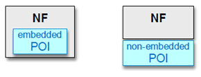
CSPs use a wide range of 3GPP NFs to provide services to users. In order to intercept a service, POIs are associated with specific NFs, as depicted in Figure 8.5-1. The manner the POI obtains the required information from the NF depends on the service and can range from something as simple as a copy-and-forward mechanism, to sophisticated isolation and filtering. The POI may be embedded in the NF or external to the NF, connected to its interfaces. The choice of one, the other, or both approaches is service specific.

In Figure 8.5-2 and Figure 8.5-3 the POI will be depicted straddling the edge of the NF to simultaneously indicate both approaches.
Figure 8.5-2 shows the basic job of a POI: to obtain the state, or communicated user data, of the intercepted service. As the NF changes state, or as additional user data is generated or forwarded, in the course of providing the service, the appropriate interceptable events or real-time content are transferred into the POI.

Although the POI has access to service state in the NF and information flows in and out of the NF, the NF shall not be able to access data in the POI, for obvious security reasons, as depicted in Figure 8.5-3. If the POI is embedded, LI data leakage from the POI back into the non-secure area of the NF shall be prohibited. If the POI is not embedded, the implementation shall prohibit LI data leakage back into the NF.
The same requirements apply to TFs.

Generally, embedded POIs have full access to the state machine of the service they intercept, while external POIs have to infer the state of the intercepted service from the events detected on the interfaces or externally applied traffic filtering criteria.
8.6 Deployment considerations p. 151
8.6.1 General p. 151
This clause provides deployment considerations for Lawful Interception.
8.6.2 CC-PAG p. 151
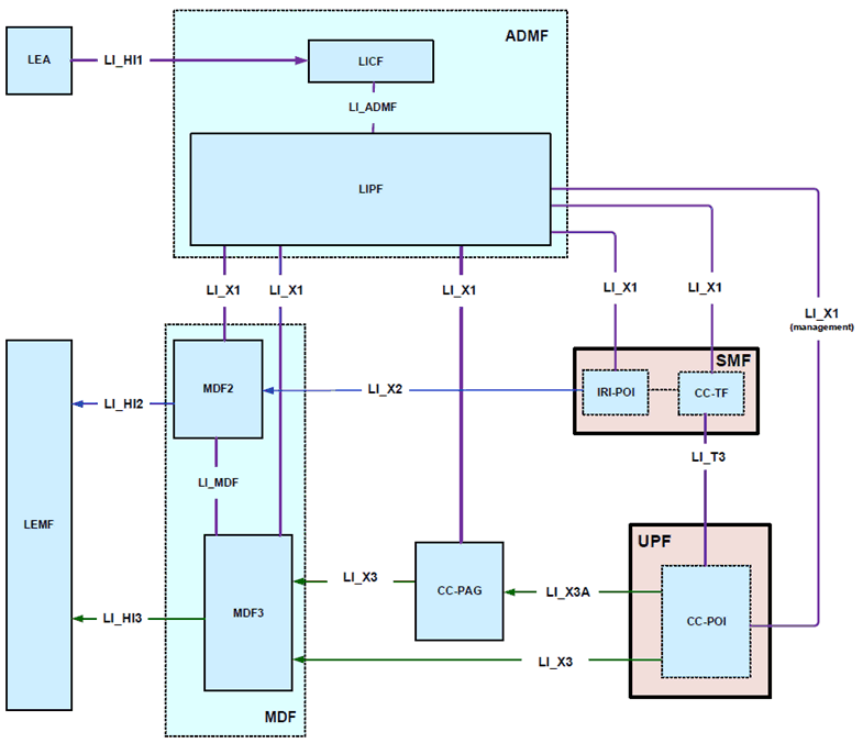
This clause introduces CC-PAG (CC-POI Aggregator) as an architectural extension that is located between the MDF3 and CC-POI. The CC-PAG performs the function of aggregating the xCC from different CC-POIs towards the MDF3 and is shown in Figure 8.6-1.

The CC-PAG is an optional LI function and may be deployed in networks that need aggregation of xCC from potentially large number of different CC-POIs towards the MDF3. The CC-PAG may be deployed closer to the UPFs, to reduce the impact of latencies, packet drops, and buffering on UPFs for lawful interception of highspeed user plane traffic. The system resources such as hardware interfaces, CPUs and memory for the CC-PAG node may be tuned to balance the forwarding/reception capabilities of CC-POI and MDF3.
As shown in Figure 8.6-1, the CC-POI is triggered by the CC-TF to deliver the xCC (on a per flow basis) to the CC-PAG (via LI_X3A interface) or to the MDF3 (via LI_X3 interface as described in clause 6.2.3).
In the option where CC-PAG is involved, the LIPF configures the CC-PAG with the appropriate MDF3 address. The CC-PAG address is provided to the CC-POI using one of the two methods:
- pre-provisioned (e.g. by LIPF over LI_X0 interface) while instructed to use the pre-provisioned address over LI_X1;
- as a part of the CC intercept trigger by the CC-TF which in turn is provisioned by the LIPF over LI_X1.