Tech-invite3GPPspaceIETFspace
21222324252627282931323334353637384‑5x
Top   in Index   Prev   Next

TS 23.214
Architecture enhancements for
Control and User Plane Separation of EPC nodes

V18.0.0 (PDF)  2024/03  101 p.
V17.0.0  2021/06  101 p.
V16.2.0  2020/09  100 p.
V15.5.0  2018/12  95 p.
V14.9.0  2018/12  95 p.
Rapporteur:
Mr. Schramm, Mirko
Huawei Technologies Co. Ltd.
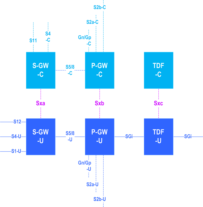
3GPP 23.214 - Architecture reference model for EPC separation of user plane and control plane

essential Table of Contents for  TS 23.214  Word version:  18.0.0

each title, in the "available" or "not available yet" area, links to the equivalent title in the CONTENT
Here   Top

Up   Top

List of Figures and Tables

Figure 4.2.1-1Architecture reference model with separation of user plane and control plane for non-roaming and roaming scenarios
Figure 4.2.2-1Architecture reference model with separation of user plane and control plane for a combined SGW/PGW
Table 4.3.1-1Existing functionality of SGW, PGW and TDF
Table 4.3.2-1Functional split of SGW
Table 4.3.2-2Functional split of PGW
Table 4.3.2-3Functional split of TDF
Table 5.2.2-1Detection information for the different UP functions and usage scenarios
Table 5.6.2-1Forwarding information for different scenarios
Figure 6.2.2-1Sx session establishment procedure
Figure 6.2.3-1Sx session modification procedure
Figure 6.2.4-1Sx session termination procedure
Figure 6.3.1.1-1Interaction between CP and UP function during PDN connection establishment
Figure 6.3.1.2.2-1Interaction between CP and UP function during procedures with SGW change (Type 1)
Figure 6.3.1.2.3-1Interaction between CP and UP function during procedures with SGW change (Type 2)
Figure 6.3.1.3-1Interaction between CP and UP function during procedures with eNB F-TEIDu update
Figure 6.3.1.4-1Interaction between CP and UP function during procedures with release of eNB F-TEIDu
Figure 6.3.1.5-1Interaction between CP and UP when downlink data is buffered in the UP function
Figure 6.3.1.6-1Interaction between CP and UP function during release of PDN connection
Figure 6.3.1.7-1Interaction between CP and UP function during modification of bearer
Figure 6.3.2.1-1Interaction between CP and UP function with IP-CAN session establishment
Figure 6.3.2.2-1Interaction between CP and UP function with IP-CAN session termination
Figure 6.3.2.3Interaction between CP and UP function with IP-CAN session modification
Figure 6.3.2.4-1Interaction between CP and UP function with PFD management
Figure 6.3.3.1-1Interaction between CP and UP function with GTP based S2b establishment
Figure 6.3.3.2-1Interaction between CP and UP function with GTP based S2a establishment
Figure 6.3.3.3-1Interaction between CP and UP function with release of GTP based S2b
Figure 6.3.3.4-1Interaction between CP and UP function with release of GTP based S2a
Figure 6.3.3.5-1Interaction between CP and UP function with dedicated bearer activation by PGW
Figure 6.3.3.6-1Interaction between CP and UP function with bearer deactivation by PGW-C
Figure 6.3.3.7-1Interaction between CP and UP function with bearer modification
Figure 6.3.3.8-1Interaction between CP and UP function with handover from non-3GPP access
Figure 6.3.3.9-1Interaction between CP and UP function with handover from 3GPP access
Figure 6.3.4.1.1-1Interaction between CP and UP function with PDN connection deactivation Group 1
Figure 6.3.4.1.1-2Interaction between CP and UP function with PDN connection deactivation Group 2
Figure 6.3.4.1.2-1Interaction between CP and UP function with PDN connection deactivation Group 1
Figure 6.3.4.1.2-2Interaction between CP and UP function with PDN connection deactivation Group 2
Figure 6.3.4.2.1-1Interaction between CP and UP function with PDN connection modification, Group 1
Figure 6.3.4.2.1-2Interaction between CP and UP function with PDN connection modification, Group 2
Figure 6.3.4.2.1-3Interaction between CP and UP function with PDN connection modification, Group 3
Figure 6.3.4.2.2-1Interaction between CP and UP function with PDN connection modification, Group 1
Figure 6.3.4.2.2-2Interaction between CP and UP function with PDN connection modification, Group 2
Figure 6.3.4.2.2-3Interaction between CP and UP function with PDN connection modification, Group 3
Figure 6.3.4.3-1Interaction between CP and UP function with PDN connection establishment
Figure 6.4.2-1Sx Session Level Reporting procedure
Figure 6.5.2-1Sx PFD Management Procedure
Table 7.2-1Session related parameters
Table 7.3-1Attributes within Packet Detection Rule
Table 7.4-1Attributes within Usage Reporting Rule
Table 7.5-1Attributes within Forwarding Action Rule
Table 7.6-1Attributes within QoS Enforcement Rule
Table 7.7-1Attributes within Usage Report
Table 7.9-1Attributes within PFD management request message

Top