Content for TS 23.292 Word version: 17.0.0
1…
4…
5…
7…
7.2…
7.3…
7.3.2.2…
7.3.2.2.4…
7.4…
7.4.2.2…
7.4.2.2.3…
7.4.2.2.7…
7.5…
7.6…
7.6.1.2.2.6…
7.6.1.2.3…
7.6.1.2.3.5…
7.6.1.2.3.6…
7.6.2…
7.6.2.7
7.6.2.8…
7.6.2.11…
7.6.3…
7.7…
7.7.2…
7.9…
7.9.2…
7.9.2.4
7.9.2.5
8…
A…
G…
H…
H.5…
H.5.3…
7.6.1.2.3.5 Explicit Communication Transfer
7.6.1.2.3.5.1 Consultative Explicit Communication Transfer
7.6.1.2.3.5.2 Blind Explicit Communication Transfer
...
...
7.6.1.2.3.5 Explicit Communication Transfer p. 75
IMS procedures as defined in TS 24.173 apply. The SCC AS combines the description of the CS bearer with the service control signalling communicated over the I1 reference point, as specified in clause 7.1.
Additionally, the SCC AS may employ an MRF for control of media as needed for execution of the Explicit Communication Transfer.
Figure 7.6.1.2.3.5.1-1 describes how IMS consultative ECT is performed when ICS UE A is playing the role of transfer initiator using I1 interface. The ICS UE A has a held call with UE B and an ongoing call with UE C before transfer.

Figure 7.6.1.2.3.5.1-1: IMS Consultative ECT via I1 for ICS UE (transfer initiator)
(⇒ copy of original 3GPP image)
(⇒ copy of original 3GPP image)
Step 1.
Figure 7.6.1.2.3.5.1-2 describes how IMS consultative ECT is performed when ICS UE is playing the role of transfer recipient using I1 interface. The UE A has a held call with UE C and also has a held call with ICS UE B before transfer.
The ICS UE A initiates transfer of UE B to UE C by sending a transfer message to SCC AS using I1 interface.
Step 2.
Completion of referring UE B to UE C as specified in TS 24.173 and releasing the session between the ICS UE A and UE C.
Step 3.
The SCC AS sends the transfer complete message to ICS UE A via I1 interface.
Step 4.
The ICS UE A releases the calls between it and UE B.

Figure 7.6.1.2.3.5.1-2: IMS Consultative ECT via I1 for ICS UE (transfer recipient)
(⇒ copy of original 3GPP image)
(⇒ copy of original 3GPP image)
Step 1.
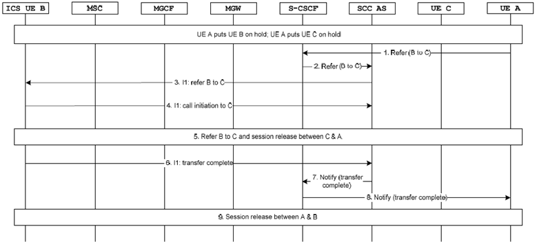
Figure 7.6.1.2.3.5.1-3 describes how IMS consultative ECT is performed when ICS UE is playing the role of transfer target using I1 interface. The UE A has a held call with UE C and also has a held call with ICS UE B before transfer.
UE A initiates transfer of ICS UE B to UE C by sending a REFER request as specified in TS 24.173.
Step 2.
The S-CSCF sends the REFER to the SCC AS as it was inserted at session establishment.
Step 3.
The S-CSCF sends a transfer message to the ICS UE B via I1 interface.
Step 4.
The ICS UE B initiates a call initiation message to SCC AS via I1 interface.
Step 5.
Completion of referring the ICS UE B to UE C as specified in TS 24.173 and releasing the session between the UE A and UE C.
Step 6.
The ICS UE B provides an indication that the communication transfer is complete to SCC AS via I1 interface.
Step 7.
The SCC AS sends a NOTIFY message to the S-CSCF.
Step 8.
The NOTIFY is sent to UE A.
Step 9.
The UE A initiates session release with ICS UE B and release the session.

Figure 7.6.1.2.3.5.1-3: IMS Consultative ECT via I1 for ICS UE (transfer target)
(⇒ copy of original 3GPP image)
(⇒ copy of original 3GPP image)
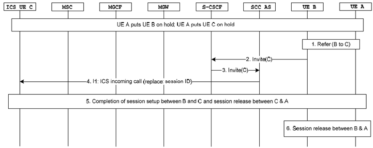
Step 1.
UE A initiates transfer of UE B to ICS UE C by sending a REFER request as specified in TS 24.173.
Step 2.
An INVITE is sent by UE B upon reception of the REFER request as specified in TS 24.173, and received at the S-CSCF of the ICS UE C.
Step 3.
The S-CSCF executes terminating initial filter criteria and forwards the INVITE message to the SCC AS.
Step 4.
The SCC AS sends an incoming call request to the ICS UE C over I1 reference point. The incoming call request indicates that a new session between UE C and UE B is to replace the current session between UE C and UE A.
Step 5.
Completion of referring UE B to the ICS UE C as specified in TS 24.173 and releasing the session between UE A and the ICS UE C.
Step 6.
UE A initiates session release with UE B and releases the session.
Figure 7.6.1.2.3.5.2-1 describes how IMS Blind ECT is performed when ICS UE A is playing the role of transfer initiator using I1 interface. The ICS UE A has a held call with UE B before transfer.

Figure 7.6.1.2.3.5.2-1: IMS Blind ECT via I1 for ICS UE (transfer initiator)
(⇒ copy of original 3GPP image)
(⇒ copy of original 3GPP image)
Step 1.
Figure 7.6.1.2.3.5.2-2 describes how IMS blind ECT is performed when ICS UE A is playing the role of transfer recipient using the I1 interface. The UE A has a held call with ICS UE B before transfer.
The ICS UE A initiates transfer of UE B to UE C by sending a transfer message to SCC AS using the I1 interface.
Step 2.
Completion of referring UE B to UE C as specified in TS 24.173 and releasing the session between the ICS UE A and UE B.
Step 3.
The SCC AS sends the transfer complete message to ICS UE A via the I1 interface.

Figure 7.6.1.2.3.5.2-2: IMS Blind ECT via I1 for ICS UE (transfer recipient)
(⇒ copy of original 3GPP image)
(⇒ copy of original 3GPP image)
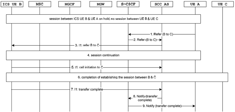
Step 1.
UE A initiates transfer of ICS UE B to UE C by sending a REFER request as specified in TS 24.173.
Step 2.
The S-CSCF sends the REFER to the SCC AS as it was inserted at session establishment.
Step 3.
The S-CSCF sends a transfer message to the ICS UE B via I1 interface.
Step 4.
Session continuation between UE A and ICS UE B as specified in clause 7.6.1.2.2.5.2, steps 5-12.
Step 5.
The ICS UE B initiates session establishment towards UE C by initiating a call initiation message to SCC AS via I1 interface.
Step 6.
Completion of session establishment between the ICS UE B and UE C as specified in clause 7.6.1.2.2.5.2, steps 15-22.
Step 7.
The ICS UE B provides indication that the communication transfer is complete to SCC AS via I1 interface.
Step 8.
The SCC AS sends a NOTIFY message to the S-CSCF.
Step 9.
The NOTIFY is sent to UE A.