Content for TS 23.292 Word version: 17.0.0
1…
4…
5…
7…
7.2…
7.3…
7.3.2.2…
7.3.2.2.4…
7.4…
7.4.2.2…
7.4.2.2.3…
7.4.2.2.7…
7.5…
7.6…
7.6.1.2.2.6…
7.6.1.2.3…
7.6.1.2.3.5…
7.6.1.2.3.6…
7.6.2…
7.6.2.7
7.6.2.8…
7.6.2.11…
7.6.3…
7.7…
7.7.2…
7.9…
7.9.2…
7.9.2.4
7.9.2.5
8…
A…
G…
H…
H.5…
H.5.3…
7.7 Session Release
7.7.1 Session Release for ICS UE
7.7.1.1 General Gm Procedures
7.7.1.2 Session Release for Gm and I1
7.7.1.3 Release of the Service Control Signalling Session when using I1
7.7.1.3.1 ICS UE Initiated Release
7.7.1.3.2 Network Initiated Release
7.7.1.3.3 Far End Initiated Release
...
...
7.7 Session Release p. 100
7.7.1 Session Release for ICS UE p. 100
7.7.1.1 General Gm Procedures p. 100
If receiving a session release from the CS access leg for the ICS UE using Gm while the PS access leg is still active, the SCC AS shall release the CS access leg. The SCC AS shall further update the remote leg, and if applicable, the PS access leg, to reflect the change of media.
7.7.1.2 Session Release for Gm and I1 p. 100
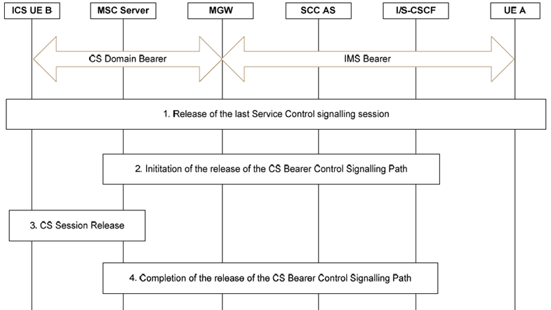
Figure 7.7.1.2-1 provides a call flow illustrating the session release procedures for an ICS UE attached to an MSC Server enhanced for ICS, which has an ICS session already established. This call flow applies when either Gm or I1 have been used to set up the Service Control Signalling Path.

Figure 7.7.1.2-1: Session Release for Gm and I1 when using an MSC server enhanced for ICS
(⇒ copy of original 3GPP image)
(⇒ copy of original 3GPP image)
Step 1.
The call flow in Figure 7.7.1.2-1 also applies when the ICS UE is attached to an MSC server.
IMS procedures are executed for the release of the service control signalling session when using the Gm reference point as defined in clause 5.10 of TS 23.228. When using I1, the procedure for the release of the service control signalling session is documented in clause 7.7.1.3.
Step 2.
The SCC AS initiates release of the CS Bearer Control Signalling Path.
Step 3.
The MSC Server releases the CS Session with the ICS UE.
Step 4.
After confirmation of the session release from the ICS UE, the MSC Server completes the release of the CS Bearer Control Signalling Path with the SCC AS. Step 4 does not have to wait for step 3 to complete.
Alternatively the ICS UE may initiate release of the CS Bearer Control Signalling Path. The SCC AS and the ICS UE shall gracefully handle the case when both the SCC AS and ICS UE initiate the release procedure.
7.7.1.3 Release of the Service Control Signalling Session when using I1 |R9| p. 101
7.7.1.3.1 ICS UE Initiated Release p. 101
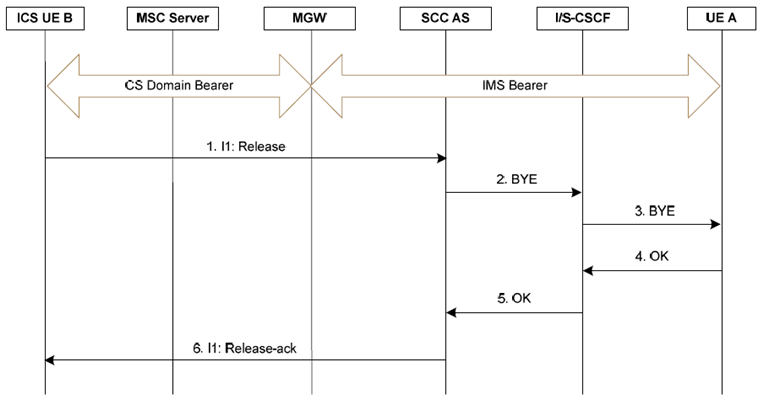
Figure 7.7.1.3.1-1 provides a call flow illustrating the release of the service control signalling session by an ICS UE regardless of whether the ICS UE is attached to MSC server enhanced for ICS or not, when using I1.

Figure 7.7.1.3.1-1: ICS UE initiated release of the service control signalling session over I1
(⇒ copy of original 3GPP image)
(⇒ copy of original 3GPP image)
Step 1.
The ICS UE sends a release over I1.
Step 2.
The SCC AS sends a SIP BYE to the I/S-CSCF serving the ICS UE.
Step 3.
The S-CSCF forward the SIP BYE to UE A.
Step 4-5.
UE A sends a SIP OK to the SCC AS via the S-CSCF of the UE B.
Step 6.
The SCC AS completes the session release procedure by sending a release-ack over I1.
7.7.1.3.2 Network Initiated Release p. 101
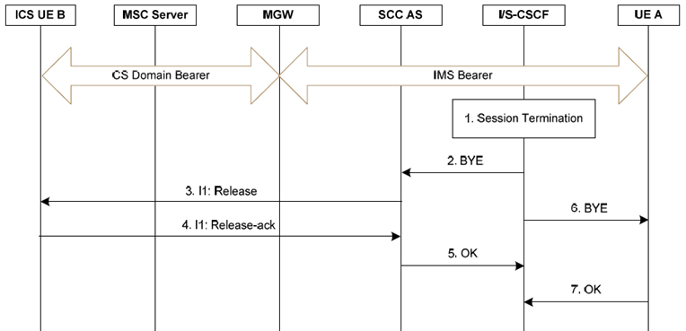
Figure 7.7.1.3.2-1 provides a call flow illustrating the release of a service control signalling session by the home IMS network regardless of whether the ICS UE is attached to MSC server enhanced for ICS or not, when using I1.

Figure 7.7.1.3.2-1: Network initiated release of a service control signalling session initiated using I1
(⇒ copy of original 3GPP image)
(⇒ copy of original 3GPP image)
Step 1.
The S-CSCF decides the session should be terminated due to administrative reasons or due to service expiration.
Steps 2-5 occur in parallel to Steps 6-7.
Step 2.
The S-CSCF sends a SIP BYE message to the SCC AS.
Step 3.
The SCC AS sends a release message over I1 to the ICS UE.
Step 4.
The ICS UE sends a release-ack to the SCC AS over I1.
Step 5.
The SCC AS sends a SIP OK to the I/S-CSCF.
Step 6.
The S-CSCF sends a SIP BYE message to UE A.
Step 7.
UE-A acknowledges receipt of the SIP BYE and sends a SIP OK back to the S-CSCF.
7.7.1.3.3 Far End Initiated Release p. 102
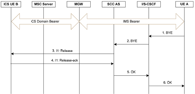
Figure 7.7.1.3.3-1 provides a call flow illustrating the release of a service control signalling session by the far end regardless of whether the ICS UE is attached to MSC server enhanced for ICS or not, when using I1.

Figure 7.7.1.3.3-1: Far End release of a service control signalling session initiated using I1
(⇒ copy of original 3GPP image)
(⇒ copy of original 3GPP image)
Step 1.
UE A terminates the session by sending a SIP BYE (via its own S-CSCF) towards the I/S-CSCF of ICS UE B.
Step 2.
The S-CSCF sends a SIP BYE message to the SCC AS.
Step 3.
The SCC AS sends a release message over I1 to the ICS UE.
Step 4.
The ICS UE sends a release-ack to the SCC AS over I1.
Step 5.
The SCC AS sends a SIP OK to the I/S-CSCF.
Step 6.
The S-CSCF sends a SIP OK message to UE A.