Content for TS 23.292 Word version: 17.0.0
1…
4…
5…
7…
7.2…
7.3…
7.3.2.2…
7.3.2.2.4…
7.4…
7.4.2.2…
7.4.2.2.3…
7.4.2.2.7…
7.5…
7.6…
7.6.1.2.2.6…
7.6.1.2.3…
7.6.1.2.3.5…
7.6.1.2.3.6…
7.6.2…
7.6.2.7
7.6.2.8…
7.6.2.11…
7.6.3…
7.7…
7.7.2…
7.9…
7.9.2…
7.9.2.4
7.9.2.5
8…
A…
G…
H…
H.5…
H.5.3…
7.3.2.2 ICS UE Originating sessions that use CS media
7.3.2.2.1 Overview
7.3.2.2.2 Originations with CS media when using I1
7.3.2.2.2.1 Originations to a SIP URI
7.3.2.2.2.2 Originations to a B-party number other than SIP-URI
7.3.2.2.3 Originations with CS media when not using I1
...
...
7.3.2.2 ICS UE Originating sessions that use CS media p. 33
7.3.2.2.1 Overview p. 33
IMS service control is used for ICS UE originated sessions that use a CS media bearer.
When using the Gm reference point, the ICS UE initiates a standard IMS originating session indicating use of CS media bearer for the session. The SCC AS is inserted in the IMS session path using originating iFC. The ICS UE also sets up a standard CS originated session addressing a PSI DN associated with the SCC AS to establish the CS bearer if a CS bearer is not available for the ICS UE. The CS bearer shall be reused if already established using the Gm reference point. The service control signalling is combined with the description of the CS bearer at the SCC AS for presentation of the IMS originating session to the S-CSCF over the Remote Leg.
When a subsequent session origination with different CS bearer requirement occurs (i.e. CS audio bearer is changed to CS video bearer, or vice versa), the CS bearer shall be updated if possible through SCUDIF or redial (refer to clause 7.9.2).
The ICS UE should be able to detect an emergency session establishment request. If the ICS UE using a CS access detects the request for the establishment of an emergency session, the ICS UE shall attempt to initiate a CS emergency call.
If the ICS UE could not detect an emergency call and originates the session with CS media using Gm reference point, it will forward an IMS session establishment request to the P-CSCF. If the P-CSCF detects such an emergency call, it rejects the request with an indication that this is for an emergency session as described in TS 23.167.
As described in TS 23.167, an ICS UE that initiated a non UE detectable emergency session will receive an indication in responses from which it can deduce that the session is for emergency. Upon receiving an emergency session rejection or session rejection with this indication, the ICS UE shall fall back to CS according to TS 23.167.
When not using the Gm reference point, the following apply:
- For sessions originated using a B party's SIP URI (not using user = phone), the ICS UE initiates a dialogue with the SCC AS over the I1 reference point indicating session origination. The ICS UE also sets up a CS originated session addressing a PSI DN associated with the SCC AS to establish the CS bearer. The service control signalling is combined with the description of the CS bearer at the SCC AS for presentation of the IMS originating session to the S-CSCF over the Remote Leg.
- For all other cases, the ICS UE initiates a standard CS originating call using B party's E.164 number. The call is routed to IMS via a standard MSC Server using IN (e.g. CAMEL) based redirection or an MSC Server enhanced with ICS. If the B party number is detected by the MSC Server as an emergency number then it will be handled as per existing MSC Server call handling procedures. Additionally, the ICS UE may use the I1 reference point for communication of additional parameters.
- When the ICS UE is attached to the MSC Server enhanced for ICS, after the multimedia connection is established, the MSC Server enhanced for ICS shall perform the video codec negotiation for the ICS UE and set up the video media bearer based upon the procedures defined in TS 29.163 for 3GPP systems and based on the procedures defined in 3GPP2 C.S0042 [38] for 3GPP2 systems;
- When the ICS UE is attached to the MSC Server not enhanced for ICS, the MGCF/IMS-MGW shall perform the video codec negotiation for the ICS UE and set up the video media bearer as specified in TS 29.163 for 3GPP systems and as specified in 3GPP2 C.S0042 [38] for 3GPP2 systems.
- if this policy is set to "Gm disabled", then the ICS UE shall not use the procedure specified in clause 7.3.2.2.4.
-
if this policy is set to "Gm enabled but not preferred", then:
- if the destination is a Tel URI or a SIP-URI representing a telephone number, and the exchange of additional SIP parameters is not required, then the ICS UE shall not use the procedure specified in clause 7.3.2.2.4;
- otherwise, the ICS UE shall use the procedure specified in clause 7.3.2.2.4.
- if this policy is set to "Gm enabled", then the ICS UE shall use the procedure specified in clause 7.3.2.2.4.
7.3.2.2.2 Originations with CS media when using I1 |R9| p. 34
7.3.2.2.2.1 Originations to a SIP URI p. 34
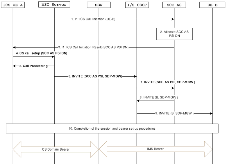
Figure 7.3.2.2.2.1-1 provides an example flow for a session origination by an ICS UE when a SIP-URI is used to address the called party and when the ICS UE is attached to an MSC Server enhanced for ICS and the user is identified as an ICS user.

Figure 7.3.2.2.2.1-1: ICS UE Origination with CS media addressing a SIP-URI when using an MSC Server enhanced for ICS
(⇒ copy of original 3GPP image)
(⇒ copy of original 3GPP image)
Step 1.
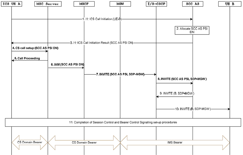
Figure 7.3.2.2.2.1-2 provides an example flow for a session origination by an ICS UE when a SIP-URI is used to address the called party and when the ICS UE is attached to an MSC Server.
The ICS UE A initiates a call by sending an ICS Call Initiation Request over the I1 reference point containing the UE B address.
Step 2.
The SCC AS performs the necessary adaptation of the signalling received over the I1 reference point. The SCC AS allocates a PSI DN and sends it to the ICS UE A.
Step 3.
The SCC AS sends the SCC AS PSI DN to the UE over the I1 reference point.
Step 4.
The ICS UE A uses standard CS originating procedures to establish a CS Bearer Control Signalling Path with the SCC AS by sending a SETUP message to the MSC Server containing the SCC AS PSI DN.
Step 5.
The MSC Server responds with a Call Proceeding message and begins to set up the CS Bearer Control Signalling Path.
Step 6.
The MSC Server sends an INVITE to the S-CSCF with the Request-URI set to the SCC AS PSI. If a GRUU is to be included as described in TS 23.228, then include a temporary-GRUU as the contact address if privacy has been requested or public-GRUU if privacy has not been requested. The MSC Server adds the User Location Information (e.g. CGI or SAI) and/or UE Time Zone Information to the INVITE.
Step 7.
The S-CSCF carries out standard processing of originating initial filter criteria and sends the INVITE to the SCC AS. The SCC AS is the first AS inserted in the session path.
Step 8.
The SCC AS invokes a B2BUA, terminating the UE Leg and originating the Remote Leg for presentation of an IMS session towards the B-party on behalf of ICS UE A. The SCC AS correlates the CS bearer control signalling session with the service control signalling session using the SCC AS PSI and creates a SIP INVITE containing the SDP received in the CS Bearer Control Signalling Path, indicating CS voice or voice and video media. The INVITE request is routed from the SCC AS to the S-CSCF.
Step 9.
The S-CSCF continues with standard IMS originated session processing and routes the request onwards to the B-party.
Step 10.
Completion of the Service Control Signalling Path and the CS Bearer Control Signalling Path setup procedures. For video call, to complete the session and bearer setup, the specific handling as described in clause 7.3.2.2.1 applies.

Figure 7.3.2.2.2.1-2: ICS UE Origination with CS media addressing a SIP-URI when using an MSC Server
(⇒ copy of original 3GPP image)
(⇒ copy of original 3GPP image)
Steps 1-5 in Figure 7.3.2.2.2.1-2 are identical to steps 1-5 in Figure 7.3.2.2.2.1-1.
At Steps 6 and 7, the MSC Server sends the IAM using the SCC AS PSI DN to an MGCF which is subsequently inter-worked to an INVITE.
Steps 8-11 in Figure 7.3.2.2.2.1-2 are identical to steps 7-10 in Figure 7.3.2.2.2.1-1.
7.3.2.2.2.2 Originations to a B-party number other than SIP-URI p. 36
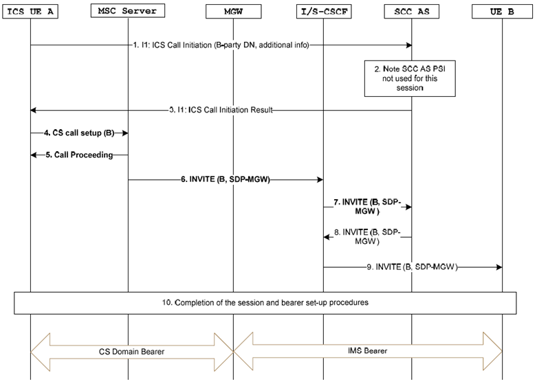
Figure 7.3.2.2.2.2-1 provides an example flow for a session origination by an ICS UE where the I1 reference point is used to set up the session and the user dials a E.164 number, Tel-URI or SIP-URI user=phone, and when the ICS UE is attached to an MSC Server enhanced for ICS and the user is identified as an ICS user.

Figure 7.3.2.2.2.2-1: ICS UE Origination with CS media using a E.164 number, Tel-URI or SIP-URI user=phone and an MSC Server enhanced for ICS
(⇒ copy of original 3GPP image)
(⇒ copy of original 3GPP image)
Step 1.
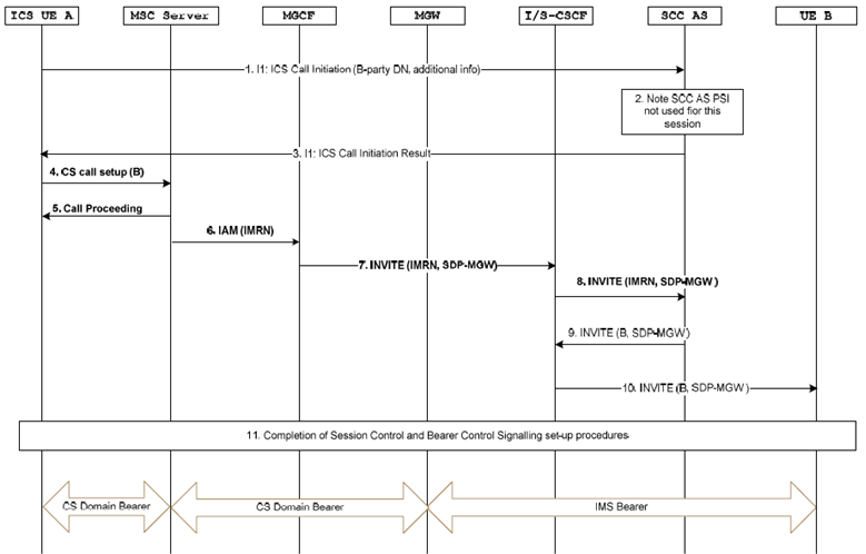
Figure 7.3.2.2.2.2-2 provides an example flow for a session origination by an ICS UE where the I1 reference point is used to set up the session and the user dials a E.164 number, Tel-URI or SIP-URI user=phone and when the ICS UE is attached to an MSC Server.
The ICS UE A initiates a call by sending an ICS Call Initiation Request over the I1 reference point containing the UE B address. The ICS UE A also indicates in the I1 message that an SCC AS PSI DN is not needed for this session.
Step 2.
The SCC AS performs the necessary adaptation of the signalling received over the I1 reference point. The SCC AS notes the SCC AS PSI DN is not used for this session.
Step 3.
The SCC AS returns an ICS Call Initiation Result to ICS UE A over the I1 reference point.
Step 4.
The ICS UE A uses standard CS originating procedures to establish a CS Bearer Control Signalling Path with the IUA of the SCC AS by sending a SETUP message to the MSC Server containing the B-party-number. If the B party number is detected by the MSC Server as an emergency number then it will be handled as per existing MSC Server call handling procedures.
When the user dials a Non-UE detectable Emergency DN or Emergency URI but I1 has been established, or if the CS origination fails to be routed into IMS, a timer running at the SCC AS will expire as the CS Bearer Control Signalling Path was not established towards the SCC AS and an appropriate indication is returned to the UE The UE shall not release the CS bearer on receipt of this indication and the UE shall not use the Service Control Signalling Path further for the call.
Step 5.
The MSC Server responds with a Call Proceeding message and begins to set up the CS Bearer Control Signalling Path.
Step 6.
The MSC Server sends an INVITE to the S-CSCF with the destination set to the called party number and the source to the calling party. If a GRUU is to be included as described in TS 23.228, then include a temporary-GRUU as the contact address if privacy has been requested or public-GRUU if privacy has not been requested. The MSC Server adds the User Location Information (e.g. CGI or SAI) and/or UE Time Zone Information to the INVITE.
Step 7.
The S-CSCF carries out standard processing of originating initial filter criteria and sends the INVITE to the SCC AS.
Step 8.
The SCC AS invokes a B2BUA, terminating the UE Leg and originating the Remote Leg for presentation of an IMS session towards the B-party on behalf of ICS UE A. The IUA correlates the CS bearer control signalling session with the service control signalling session and creates a SIP INVITE containing the SDP received in the CS Bearer Control Signalling Path, indicating CS voice or voice and video media and routes the INVITE request to the S-CSCF. If the SCC AS obtains the calling party identify from step 1, then the SCC AS shall use this identity from step 1 as the calling party identity. Otherwise, then the SCC AS shall use the calling party identity received in step 6.
Step 9.
The S-CSCF continues with standard IMS originated session processing and routes the request onwards to the B-party.
Step 10.
Completion of the Service Control Signalling Path and the CS Bearer Control Signalling Path setup procedures. For video call, to complete the session and bearer setup, the specific handling as described in clause 7.3.2.2.1 applies.

Figure 7.3.2.2.2.2-2: ICS UE Origination with CS media using a E.164 number, Tel-URI or SIP-URI user=phone and an MSC Server
(⇒ copy of original 3GPP image)
(⇒ copy of original 3GPP image)
Steps 1-5 in Figure 7.3.2.2.2.2-2 are identical to steps 1-5 in Figure 7.3.2.2.2.2-1.
In Steps 6 and 7, IN (e.g. CAMEL) origination triggers are used at the MSC Server for fetching of an IP Multimedia Routing Number (IMRN). The MSC Server sends an IAM to an MGCF using the IMRN which is subsequently inter-worked to an INVITE.
In Step 8, the S-CSCF carries out standard processing of originating initial filter criteria and sends the INVITE to the SCC AS. This step is skipped if the I-CSCF routes the INVITE request directly to the SCC AS.
Steps 9-11 in Figure 7.3.2.2.2.2-2 are identical to steps 8-10 in Figure 7.3.2.2.2.2-1.
7.3.2.2.3 Originations with CS media when not using I1 p. 39
This procedure may be used when the ICS User dials an E.164 number, a Tel URI or a SIP-URI user=phone, and the exchange of additional SIP parameters is not required. The ICS UE initiates a standard CS originating using the B-party's E.164 number or a number derived from the Tel-URI. The call is routed to IMS via an MSC Server which is enhanced to support ICS or a standard MSC Server using IN (e.g. CAMEL) based re-direction.
Figure 7.3.2.1.2-1 provides an example flow for a session origination by an ICS UE where the I1 reference point is not required to set up the session and a MSC Server enhanced for ICS is used to set-up the CS Bearer Control Signalling Path and the user is identified as an ICS user.
For a session origination by an ICS UE where the I1 reference point is not required to set up the session and a MSC Server enhanced for ICS is not used to set-up the CS bearer control signalling, an example call flow is shown in Figure 7.3.2.1.3-1.