Content for TS 23.292 Word version: 17.0.0
1…
4…
5…
7…
7.2…
7.3…
7.3.2.2…
7.3.2.2.4…
7.4…
7.4.2.2…
7.4.2.2.3…
7.4.2.2.7…
7.5…
7.6…
7.6.1.2.2.6…
7.6.1.2.3…
7.6.1.2.3.5…
7.6.1.2.3.6…
7.6.2…
7.6.2.7
7.6.2.8…
7.6.2.11…
7.6.3…
7.7…
7.7.2…
7.9…
7.9.2…
7.9.2.4
7.9.2.5
8…
A…
G…
H…
H.5…
H.5.3…
7.4.2.2 ICS UE Terminating sessions that use CS media
7.4.2.2.1 Overview
7.4.2.2.2 Terminations with CS media using the Gm reference point
...
...
7.4.2.2 ICS UE Terminating sessions that use CS media p. 46
7.4.2.2.1 Overview p. 46
IMS service control is used for ICS UE terminating sessions that use CS media.
All ICS User incoming sessions are directed to IMS for delivery to the ICS User. The SCC AS is inserted in the IMS session path using the terminating iFCs. The SCC AS performs T-ADS for selection of a contact address amongst the registered contact addresses for the ICS User and subsequently selects an access network for delivery of the session to the selected contact address.
When using the Gm reference point for delivery of the incoming session to the ICS UE, the SCC AS directs the IMS terminating session toward the ICS User's selected contact indicating use of CS bearer for the session. On receipt of the session initiating message, the ICS UE sets up a standard CS originated session addressing a PSI DN associated with the SCC AS to establish the CS bearer if a CS bearer is not available for the ICS UE. The CS bearer shall be reused if already established using the Gm reference point. The service control signalling is combined with the description of the CS bearer at the SCC AS for presentation of IMS terminating session to the S-CSCF over the Remote Leg.
When a subsequent session termination with different CS bearer requirement occurs (i.e. CS audio bearer is changed to CS video bearer, or vice versa), the CS bearer shall be updated if possible through SCUDIF or redial (refer to clause 7.9.2).
The following clauses show pairs of flows, one for an ICS UE when using an MSC Server and the other for an MSC Server enhanced for ICS. They are for the most part identical except that in the case of an MSC Server enhanced for ICS the INVITE towards the SCC AS is sent directly from the MSC Server otherwise an MSC sends an ISUP IAM and the MGCF interworks this to an INVITE towards the SCC AS.
For video call terminating sessions that use CS media, the following apply:
- When the ICS UE is attached to the MSC Server enhanced for ICS, after the multimedia connection is established, the MSC Server enhanced for ICS shall perform the video codec negotiation for the ICS UE and set up the video media bearer based upon the procedures defined in TS 29.163 for 3GPP systems and based on the procedures defined in 3GPP2 C.S0042 [38] for 3GPP2 systems;
- When the ICS UE is attached to the MSC Server not enhanced for ICS, the MGCF/IMS-MGW shall perform the video codec negotiation for the ICS UE and set up the video media bearer as specified in TS 29.163 for 3GPP systems and as specified in 3GPP2 C.S0042 [38] for 3GPP2 systems.
7.4.2.2.2 Terminations with CS media using the Gm reference point p. 46
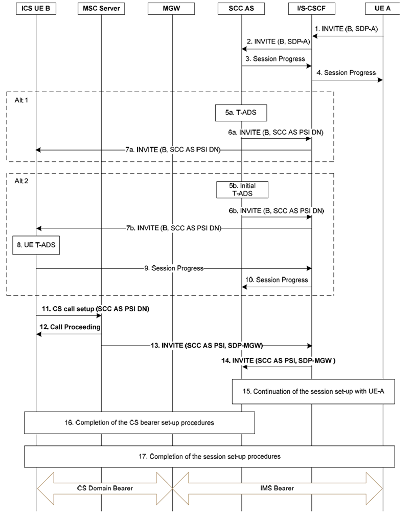
Figure 7.4.2.2.2-1 provides an example flow for a call destined to an ICS UE attached to an MSC server enhanced for ICS, where the incoming session is delivered over the Gm reference point and the media is established via the CS network.

Figure 7.4.2.2.2-1: ICS UE Terminations with CS media information flows using Gm reference point when using an MSC Server enhanced for ICS
(⇒ copy of original 3GPP image)
(⇒ copy of original 3GPP image)
Step 1.
Steps 5a - 7a are for the case of T-ADS performed by the SCC AS.
An incoming SIP INVITE is received at the S-CSCF of the B party from UE A.
Step 2.
The S-CSCF executes terminating initial filter criteria and forwards the INVITE to the SCC AS.
Step 3.
The SCC AS sends a Session Progress response to the S-CSCF.
Step 4.
The S-CSCF forwards the Session Progress response to UE A.
Step 5a.
The SCC AS performs Terminating Access Domain Selection and chooses the CS domain for the setup of the media.
Step 6a.
The SCC AS terminates the session from the A-party and establishes a new session by sending an INVITE to the B-party via the I/S-CSCF. This INVITE contains an indication to inform the UE to initiate the CS bearer establishment procedure. The INVITE also contains a dynamic SCC AS PSI to enable the SCC AS to later on correlate the outgoing service control signalling with the incoming CS bearer control signalling. When the T-ADS function selects the Gm reference point for service control the SCC AS prevents the S-CSCF from selecting the contact address of the MSC Server, and the S-CSCF selects the IP-CAN
Step 7a.
The I/S-CSCF sends the INVITE to B-party.
Step 5b.
Alternatively, in the case of UE T-ADS as defined in clause 5.3.1, the SCC AS performs initial T-ADS selecting IMS for the service control signalling when UE-B is registered in the IMS.
Step 6b.
The SCC AS terminates the session from the A-party and establishes a new session by sending an INVITE to the B-party via the I/S-CSCF. The INVITE contains options that enable UE-B to choose a CS bearer for bidirectional speech media transport if it determines that this is not supported by serving PS Access Network. The INVITE also contains a dynamic SCC AS PSI to enable the SCC AS to later on correlate the outgoing service control signalling with the incoming CS bearer control signalling. When the T-ADS function selects the Gm reference point for service control, the SCC AS prevents the S-CSCF from selecting the contact address of the MSC Server, and the S-CSCF selects the IP-CAN.
Step 7b.
The I/S-CSCF sends the INVITE to B-party.
Step 8-10.
UE-B responds with a Session Progress message. In the case that the PS access network does not support bidirectional speech media and in the event the "IMS voice over PS session supported indication" indicates voice is not supported as defined in clause 4.3.5.8 of TS 23.401, UE-B shall indicate in the Session Progress message that a CS bearer is required for the bidirectional speech component of the session and that the Gm reference point is used for service control. The S-CSCF forwards the Session Progress message to the SCC AS.
Step 11.
For video call, in Steps 16 and 17, to complete the session and bearer setup, the specific handling as described in clause 7.4.2.2.1 applies.
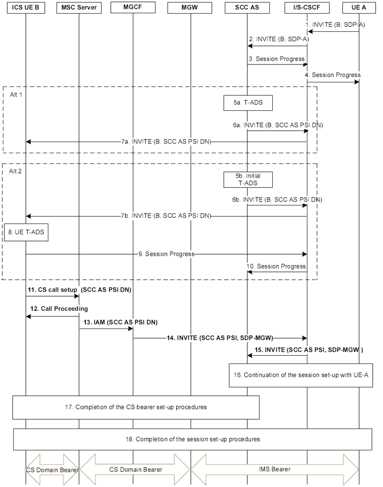
Figure 7.4.2.2.2-2 provides an example flow for a call destined to an ICS UE attached to an MSC server, where the incoming session is delivered over the Gm reference point and the media is established via the CS network.
If the establishment mechanism is for UE originated, the ICS UE sends a CS call setup message to the MSC Server using the SCC AS PSI DN to establish the CS Bearer Control Signalling Path. This will establish the circuit bearer between the UE and IMS.
Step 12.
The MSC Server responds with a call proceeding message and begins to set up the CS Bearer Control Signalling Path.
Step 13.
The MSC Server sends an INVITE towards the I/S-CSCF containing the SCC AS PSI and an SDP Offer with the media description from the MGW. The MSC Server adds the User Location Information (e.g. CGI or SAI) and/or UE Time Zone Information to the INVITE.
Step 14.
The I/S-CSCF forwards the INVITE to the SCC AS.
Step 15.
The SCC AS continues the session setup towards the A-party for the original INVITE in Step 1. The response contains an SDP answer with the media description from the SDP offer received in Step 13.
Step 16.
The SCC AS completes the set-up of the CS Bearer Signalling Path towards ICS UE B which involves sending a 200 OK in response to the INVITE in Step 14. The ICS UE B, the MSC Server and the SCC AS complete the setup of the CS Bearer Control Signalling Path and the Service Control Signalling Path with UE A.
Step 17.
The ICS UE B continues with the set-up of the Service Control Signalling Path towards the UE A which includes sending a Ringing response to the SCC AS via the S-CSCF. The ICS UE B then completes the set-up of the Service Control Signalling Path towards the Remote End which includes sending a final 200 OK message in response to the INVITE received at steps 7a or 7b.

Figure 7.4.2.2.2-2: ICS UE Terminations with CS media information flows using Gm reference point when using an MSC Server
(⇒ copy of original 3GPP image)
(⇒ copy of original 3GPP image)
Steps 1-12 in Figure 7.4.2.2.2-2 are identical to steps 1-12 in Figure 7.4.2.2.2-1.
At Steps 13 and 14, the MSC server sends the IAM to an MGCF using the SCC AS PSI DN which is subsequently inter-worked to an INVITE containing the SCC AS PSI and an SDP Offer from the MGW.
Steps 15-18 in Figure 7.4.2.2.2-2 are identical to steps 14-17 in Figure 7.4.2.2.2-1.