Content for TS 23.284 Word version: 17.0.0
1…
4…
4.2…
4.3…
5
6…
6.3…
6.3.2
6.3.3
6.3.4
6.3.5
7…
7.2.4…
7.2.4.2
7.2.4.3
7.2.4.4
7.2.4.5
7.2.4.6
7.3…
7.3.4…
7.3.4.2
7.3.4.3
7.3.4.4
8…
8.2.3
8.3…
8.3.2
8.4…
8.4.1.1.7…
8.4.1.2…
8.4.2…
8.4.2.2…
8.4.5…
8.4.5.6
8.4.5.7
8.4.5.8…
9…
13…
13.4…
13.4.3…
13.4.4…
13.5…
13.6…
13.7…
14…
16…
A…
A.2…
8.4.1.1.7 Example
8.4.1.1.7.1 Connection Model
8.4.1.1.7.2 Basic Sequence for Inter-BSS Handover that breaks Local Switching
...
...
8.4.1.1.7 Example p. 92
8.4.1.1.7.1 Connection Model p. 92
Figure 8.4.1.1.7.1.1 shows the network model for the Intra-MSC Inter-BSS GSM to GSM Handover, where the call leg pertinent to the UE-1 is handed over from the serving BSS-1 to the Target BSS. BSS-1 is the same as BSS-2 when LCLS is established for the call. The bearer termination T2 is used for the bearer towards BSS-2, which is not affected by this handover. Bearer termination TS is used for the bearer towards BSS-1 and the bearer terminations T1 and TA are used for the bearer towards the succeeding/preceding MGW. Bearer termination TT is for the bearer termination towards the Target BSS. The colours and line types used in the Figure are defined differently from TS 23.205 to indicate LCLS specific issues.
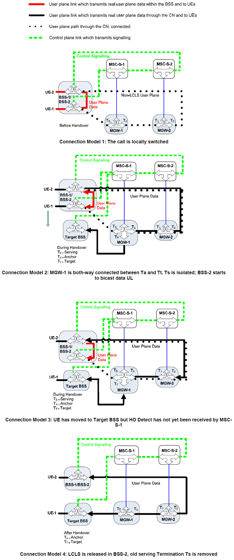
Figure 8.4.1.1.7.1.1: Intra-MSC Inter-BSS Handover Connection Model that breaks LCLS
(⇒ copy of original 3GPP image)
(⇒ copy of original 3GPP image)
8.4.1.1.7.2 Basic Sequence for Inter-BSS Handover that breaks Local Switching p. 95
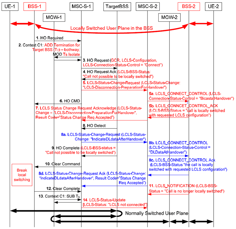
Figure 8.4.1.1.7.2.1: Intra-MSC Inter-BSS Handover that breaks Local Switching
(⇒ copy of original 3GPP image)
(⇒ copy of original 3GPP image)
Step 1.
LCLS is impossible after an Inter-BSS handover which makes the call not local (as described above). While a handover is being performed for one call leg, it is possible that a handover also is started for the other call leg, possibly moving both call legs to the same target BSS, thereby creating a local call. The target BSS shall only establish LCLS for a local call when both call legs are connected and e.g. any handover process has been successfully completed on both call legs.
The Handover Required message is received from the BSS-1 requesting an inter-BSS handover. The call is currently locally switched so the MSC-1 server can know that the inter-BSS handover at one end will break local switch (the local switch is not broken in the serving BSS (BSS-1) until the UE-1 has moved out of the BSS-1 and the MSC-1 server sends the Clear Command message).
Step 2.
In this example the Anchor MSC-1 server requests from its MGW-1 the seizure of the bearer termination Tt towards the Target BSS and through-connects it bothway to Ta. Additionally it isolates the old serving Termination Ts. This makes the handover much more efficient than even current non-LCLS handover as immediately the UE-1 moves into the new target BSS it will be able to send UL user data to the UE-2.
Step 3.
The Anchor MSC-1 server sends the Handover Request message to the Target BSS with the GCR IE, the LCLS-Configuration IE and the LCLS-Connection-Status-Control IE indicating "connect" to through-connect the local call.
Step 4.
The Target BSS returns the Handover Request Acknowledge message and also indicates that call is not possible to be locally switched.
Step 5.
The Anchor MSC-1 server sends the change in LCLS to the succeeding MSC server and the Anchor MSC-1 server asks it to prepare for the LCLS disconnection for Handover to trigger sending of the LCLS-Connect-Control message at the far end MSC-2 server.
Step 5a.
The far end MSC-2 server requests the BSS-2 to start sending data UL with the LCLS_Connect_Control message and the LCLS-Connection-Status-Control IE indicating "BicastatHandover", see Figure 8.4.1.1.7.1.1 Connection Model 2. This triggers the BSS-2 to bicast the user plane data in the same way as the Access MGW-1 would be doing in a non-LCLS inter-BSS handover. At this point the BSS-2 shall send any DL data it receives directly to the served UE. Since the BSS-2 cannot receive DL data at the same time as it receives local data (Ts is isolated) this will minimise the break in user plane data even more than for existing non-LCLS handover.
Step 5b.
The BSS-2 sends the LCLS_Connect_Control_Ack message with the LCLS-BSS-Status IE set to "the call is locally switched with requested LCLS configuration".
Step 6.
The Anchor MSC-1 server triggers the Handover Command message. When the UE-1 moves to the Target BSS in this example it can immediately send UL data through the CN to the UE-2 and also can receive DL data from the UE-2 via the CN since the MGW-1 topology for Ta, Tt is already bothway connected. This is a change from the current non-LCLS solution but is more efficient since the non-LCLS solution needs to set this to one-way DL only until it receives Handover Detect message.
Step 7.
MSC-2 Server sends LCLS-Status-Change-Request-Acknowledgement.
Step 8.
The UE-1 is detected at the target BSS. The BSS-1/BSS-2 may continue to send the user plane data locally until the Clear Command message is received.
Step 8a.
The MSC-1 Server sends LCLS-Status-Change-Request to indicate that UE-1 has been detected in the target BSS and user data is now being sent through the CN and DL to the distant UE-2.
Step 8b.
The MSC-2 Server signals to the BSS-2 that DL data received from the CN is now real user data coming from the UE-1.
Step 8c.
The BSS-2 sends the LCLS_Connect_Control_Ack message with the LCLS-BSS-Status IE set to "the call is locally switched with requested LCLS configuration".
Step 8d.
Acknowledgement back through the CN that the indication for DL data after Handover Detect has been delivered.
Step 9.
In the Handover Complete message the Target-BSS indicates to the MSC-1 server in the LCLS-BSS-Status IE that the call is not possible to be locally switched.
Step 10.
The MSC-1 server requests the old serving BSS-1 to clear the old call leg. The BSS-1 now stops sending local the user data from UE-1, LCLS is finally broken.
Step 11.
The Serving BSS-2 informs the MSC-2 server that LCLS is broken via LCLS_Notification message.
Step 12.
Clearing of the old call leg to the Serving BSS-1 is completed.
Step 13.
The termination Ts to the old serving BSS-1 is removed from the Access MGW-1.
Step 14.
The Anchor MSC-1 server informs succeeding CN nodes that LCLS is finally disconnected.
![]()
![]()
![]()