Content for TS 23.284 Word version: 17.0.0
1…
4…
4.2…
4.3…
5
6…
6.3…
6.3.2
6.3.3
6.3.4
6.3.5
7…
7.2.4…
7.2.4.2
7.2.4.3
7.2.4.4
7.2.4.5
7.2.4.6
7.3…
7.3.4…
7.3.4.2
7.3.4.3
7.3.4.4
8…
8.2.3
8.3…
8.3.2
8.4…
8.4.1.1.7…
8.4.1.2…
8.4.2…
8.4.2.2…
8.4.5…
8.4.5.6
8.4.5.7
8.4.5.8…
9…
13…
13.4…
13.4.3…
13.4.4…
13.5…
13.6…
13.7…
14…
16…
A…
A.2…
6.3.5 LCLS established, Basic Call Example with BICC based CS core network, backward bearer establishment p. 43
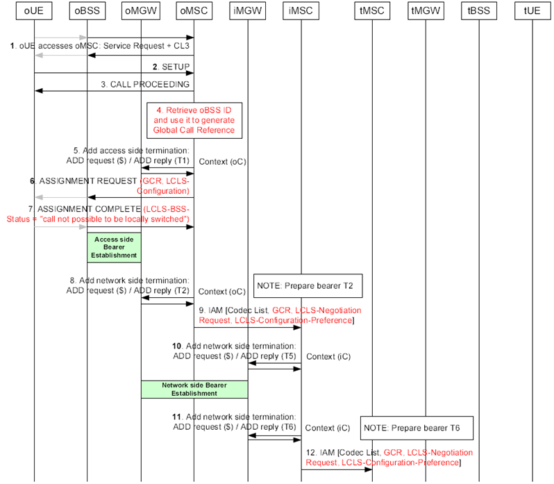
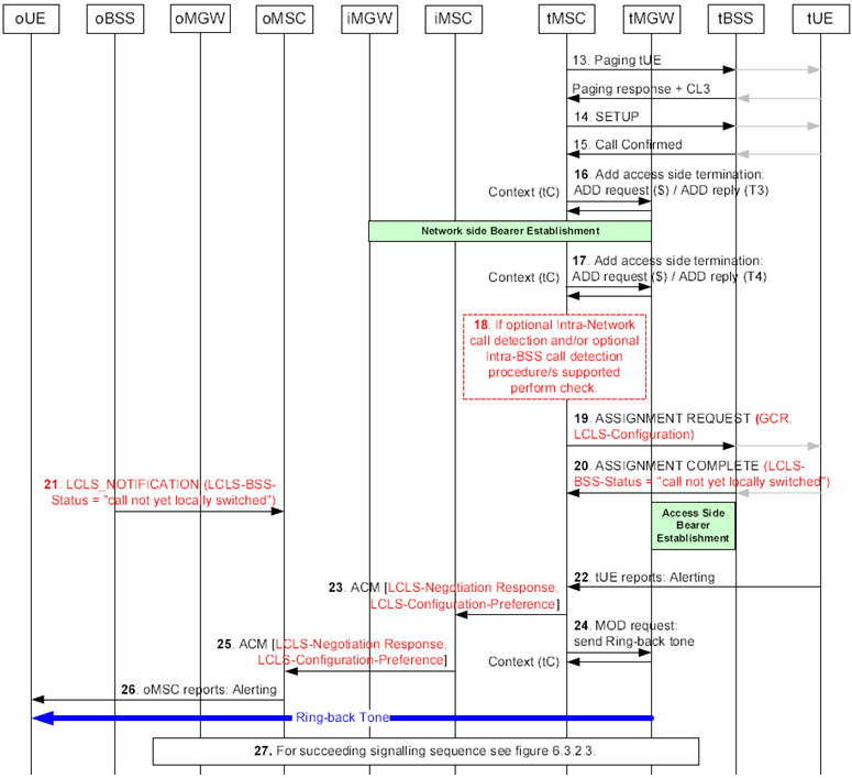
Figure 6.3.5.1 and Figure 6.3.5.2 show the message sequence example for the basic call establishment for LCLS. In this example the oUE and the tUE belong to the same BSS (marked as oBSS and tBSS) and the CN permits LCLS. The example is based on examples from TS 23.205 for the basic mobile originating call, backward bearer establishment (case when access bearer assignment is completed before sending of initial address message) and the basic mobile terminating call, backward bearer establishment.

Figure 6.3.5.1: Basic Call Establishment Flow when call is locally switched, backward bearer establishment
(⇒ copy of original 3GPP image)
(⇒ copy of original 3GPP image)
Step 1.
Service Request handling.
Step 2.
Originating Call SETUP.
Step 3.
The oMSC server replies with the CALL PROCEEDING message to indicate that the call is being processed.
Step 4.
If the oMSC server supports LCLS it retrieves the oBSS ID and generates the Global Call Reference for the call.
Step 5.
Before the network side bearer information is seized the oMSC server requests the seizure of the access side bearer termination.
Step 6.
The oMSC server includes a preliminary LCLS-Configuration IE in the ASSIGNMENT REQUEST message along with the GCR IE, because the oMSC server does not know whether LCLS is allowed in the core network at this stage.
Step 7.
The oBSS returns the ASSIGNMENT COMPLETE message with the LCLS-BSS-Status IE indicating "call not possible to be locally switched".
Step 8.
The oMSC server prepares the seizure of the network side bearer termination.
Step 9.
Afer the oMGW has replied with the bearer address and the binding reference, the oMSC server sends the IAM to the succeeding node, in which the oMSC server indicates that backward bearer establishment is to be used. The oMSC server sends the IAM message including supported codecs list, GCR with encapsulated oBSS ID, the LCLS-Negotiation Request IE and the LCLS-Configuration-Preference IE.
Step 10.
When the initial address and the bearer information is received the iMSC server requests the seizure of the network side bearer termination.
Step 11.
The iMSC server prepares the seizure of the outgoing side bearer termination.
Step 12.
Afer the iMGW has replied with the bearer address and the binding reference, the iMSC server sends the IAM to the succeeding node. If the iMSC server supports LCLS it may modify the LCLS-Negotiation IE due to CAMEL, supplementary service requirements etc. before sending the IAM message containing the GCR with the encapsulated oBSS ID, the LCLS-Negotiation Request IE and the LCLS-Configuration-Preference IE.

Figure 6.3.5.2: Basic Call Establishment when call is locally switched, backward bearer establishment (continuation of Figure 6.3.5.1)
(⇒ copy of original 3GPP image)
(⇒ copy of original 3GPP image)
Step 13.
The tMSC server pages the tUE.
Step 14.
The tMSC server performs call Setup.
Step 15.
The tUE confirms the call.
Step 16.
The tMSC server requests the tMGW to establish a bearer to the given iMGW.
Step 17.
The tMSC server requests the seizure of the access side bearer termination.
Step 18.
If the tMSC server supports the optional "intra-Network call detection" procedure it compares its own Network ID with the Network ID received within the Global Call Reference IE.
If the tMSC server supports the optional "intra-BSS call detection" procedure it compares the BSS ID of the selected terminating BSS with the oBSS ID received within the Global Call Reference IE at this step. Since the oUE and the tUE belong to the same BSS the call continues the same way as for the basic LCLS establishment without this pre-check.
Step 19.
The tMSC server performs the access bearer assignment and sends the ASSIGNMENT REQUEST message containing the GCR IE and the LCLS-Configuration IE if LCLS is permitted in the core network.
Step 20.
The oBSS/tBSS performs the GCR correlation. Since the GCR correlation has identified the call as an intra BSS call and LCLS is allowed in the BSS, the tBSS returns the ASSIGMENT COMPLETE message with the LCLS-BSS-Status IE indicating "Call not yet locally switched".
Step 21.
Since the GCR correlation has identified the call as an intra BSS call and LCLS is allowed in the BSS, the oBSS signals the LCLS status change by sending the LCLS_NOTIFICATION message with the LCLS-BSS-Status IE set to "Call not yet locally switched".
Step 22.
The tUE reports alerting.
Step 23.
The tMSC server returns the ACM message and includes the LCLS-Negotiation Response IE and the LCLS-Configuration-Preference IE if LCLS is supported.
Step 24.
The tMSC requests the tMGW to provide a ring-back tone.
Step 25.
The iMSC server returns the ACM message and includes the LCLS-Negotiation Response IE and the LCLS-Configuration-Preference IE.
Step 26.
The oMSC server reports alerting.
Step 27.
When performing further call establishment see Figure 6.3.2.3.