Content for TS 23.284 Word version: 17.0.0
1…
4…
4.2…
4.3…
5
6…
6.3…
6.3.2
6.3.3
6.3.4
6.3.5
7…
7.2.4…
7.2.4.2
7.2.4.3
7.2.4.4
7.2.4.5
7.2.4.6
7.3…
7.3.4…
7.3.4.2
7.3.4.3
7.3.4.4
8…
8.2.3
8.3…
8.3.2
8.4…
8.4.1.1.7…
8.4.1.2…
8.4.2…
8.4.2.2…
8.4.5…
8.4.5.6
8.4.5.7
8.4.5.8…
9…
13…
13.4…
13.4.3…
13.4.4…
13.5…
13.6…
13.7…
14…
16…
A…
A.2…
6.3.4 LCLS established, Basic Call Example with SIP-I based CS core network p. 37
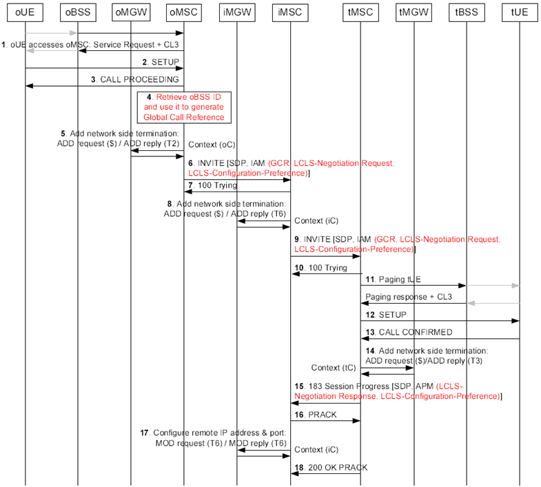
Figure 6.3.4.1, Figure 6.3.4.2, Figure 6.3.4.3 and Figure 6.3.4.4 show the message sequence example for the basic call establishment when call is locally switched. In this example the oUE and the tUE belong to the same BSS (marked as oBSS and tBSS) and the CN permits LCLS. The example is based on examples for the basic mobile originating call and for the basic mobile terminating call from TS 23.231.

Figure 6.3.4.1: Basic Call Establishment Flow when call is locally switched
(⇒ copy of original 3GPP image)
(⇒ copy of original 3GPP image)
Step 1.
Service Request handling.
Step 2.
Originating Call SETUP.
Step 3.
The oMSC server replies with a CALL PROCEEDING message to indicate that the call is being processed.
Step 4.
If the oMSC server supports LCLS it retrieves the oBSS ID and generates the Global Call Reference for the call.
Step 5.
The oMSC server selects the codec and requests the oMGW to select and provide the IP transport address and port for the network side bearer connection before sending the INVITE message.
Step 6.
The oMSC server sends the INVITE request with the initial SDP offer indicating that local preconditions have not been met, and with the encapsulated IAM message containing the GCR with encapsulated oBSS ID, the LCLS-Negotiation Request IE and the LCLS-Configuration-Preference IE.
Step 7.
The iMSC server confirms the reception of the INVITE request with a 100 Trying provisional response.
Step 8.
The iMSC server selects the codec and requests the iMGW to select and provide the IP transport address and port for the outgoing network side bearer termination.
Step 9.
If the iMSC server supports LCLS it may modify the LCLS-Negotiation Request IE and the LCLS-Configuration-Preference IE due to CAMEL, supplementary service requirements etc. before sending the INVITE request with the SDP offer and with the encapsulated IAM message containing the GCR with the encapsulated oBSS ID, the LCLS-Negotiation Request IE and the LCLS-Configuration-Preference IE.
Step 10.
The tMSC server confirms the reception of the INVITE request with 100 a Trying provisional response.
Step 11.
The tMSC server pages the tUE.
Step 12.
The tMSC server performs call Setup.
Step 13.
The tUE confirms the call.
Step 14.
The tMSC server selects the codec, provides to the tMGW the selected codec and the remote user plane IP address and port information that were received from the preceding node in the SDP offer and requests the tMGW to prepare for the network side bearer establishment.
Step 15.
After the tMGW has replied with the local IP address and port information the tMSC server includes in the SDP answer the user plane IP address and UDP port received from the tMGW, the selected codec and any additional accepted payload types. The tMSC server returns a 183 Session Progress provisional response with the SDP answer and if LCLS is supported with encapsulated APM message containing the LCLS-Negotiation Response IE and the LCLS-Configuration-Preference IE.
Step 16.
The iMSC server replies to succeeding node with the PRACK request to confirm the reception of the 183 Session Progress provisional response.
Step 17.
When the 183 Session Progress provisional response with the SDP answer is received the iMSC server requests the iMGW to configure the remote IP transport address and any additional negotiated payload types of the outgoing side bearer termination.
Step 18.
The tMSC server confirms the reception of the PRACK request with a 200 OK final response.

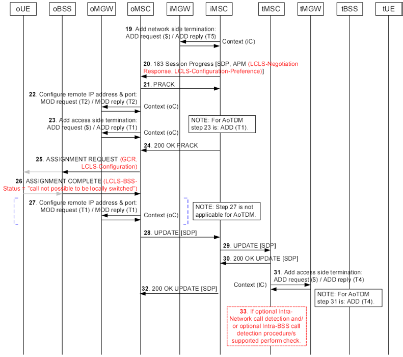
Figure 6.3.4.2: Basic Call Establishment when call is locally switched (continuation of Figure 6.3.4.1)
(⇒ copy of original 3GPP image)
(⇒ copy of original 3GPP image)
Step 19.
The iMSC server selects the codec for the incoming side bearer termination, provides to the iMGW the selected codec and the remote user plane IP address and port information that were received from the preceding node in the SDP offer and requests the iMGW to prepare for the incoming side bearer establishment.
During the seizure of the outgoing side and the incoming side bearer termination the iMSC server will also request the iMGW to through-connect the bearer terminations so that the bearer will be bothway through-connected.
Step 20.
After the iMGW has replied with the local IP address and port information the iMSC server includes in the SDP answer the user plane IP address and UDP port received from the iMGW, the selected codec and any additional accepted payload types. The iMSC server sends the 183 Session Progress provisional response with the SDP answer and with encapsulated APM message containing the LCLS-Negotiation Response IE and the LCLS-Configuration-Preference IE to the preceding node.
Step 21.
The oMSC server replies to the succeeding node with the PRACK request to confirm the reception of the 183 Session Progress provisional response.
Step 22.
The oMSC server requests the oMGW to configure the remote user plane IP address and any additional negotiated payload types of the network side bearer termination.
Step 23.
The oMSC server requests the seizure of the access side bearer termination.
During the seizure of the network side or the access side bearer termination the oMSC server will also request the oMGW to through-connect the bearer terminations so that the bearer will be backward through-connected.
Step 24.
The iMSC server confirms the reception of the PRACK request with the 200 OK final response.
Step 25.
The oMSC server determines whether LCLS is allowed in the core network based on the returned LCLS-Negotiation IE and if so the oMSC server includes the LCLS-Configuration IE in the ASSIGNMENT REQUEST message along with the GCR IE.
Step 26.
The oBSS returns the ASSIGNMENT COMPLETE message with the LCLS-BSS-Status IE indicating "call not possible to be locally switched".
Step 27.
When the oMSC server receives the ASSIGNMENT COMPLETE message, it requests the oMGW to configure the remote user plane IP address and UDP Port for the access side bearer termination.
Step 28.
Since the access bearer assignment is completed the oMSC server sends the UPDATE request with the SDP offer indicating local preconditions met to the succeeding node.
Step 29.
The iMSC server forwards the UPDATE request to the succeeding node.
Step 30.
The tMSC server confirms the reception of the UPDATE request with the 200 OK final response.
Step 31.
When the tMSC server receives the SDP offer indicating remote preconditions met it requests the seizure of the access side bearer termination.
If not requested during the seizure of network side bearer termination (step 14) the tMSC server will request the tMGW to through-connect the bearer terminations so that the bearer will be backward through-connected.
Step 32.
The iMSC server forwards the 200 OK (UPDATE) final response to the preceding node.
Step 33.
If the tMSC server supports the optional "intra-Network call detection" procedure it compares its own Network ID with the Network ID received within the Global Call Reference IE.
If the tMSC server supports the optional "intra-BSS call detection" procedure it compares the BSS ID of the selected terminating BSS with the oBSS ID received within the Global Call Reference IE at this step. Since the oUE and the tUE belong to the same BSS the call continues the same way as for the basic LCLS establishment without this pre-check.

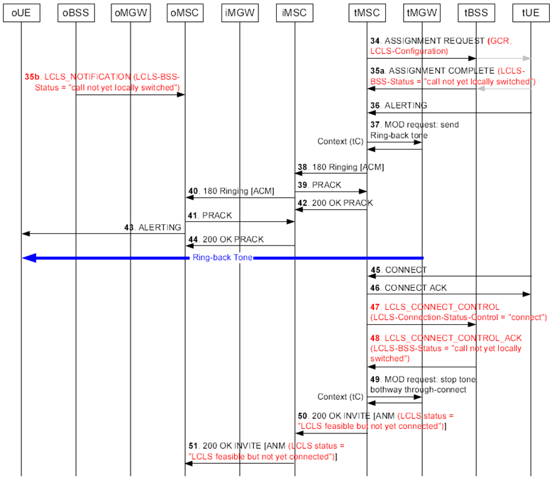
Figure 6.3.4.3: Basic Call Establishment when call is locally switched (continuation of Figure 6.3.4.2)
(⇒ copy of original 3GPP image)
(⇒ copy of original 3GPP image)
Step 34.
The tMSC server sends the ASSIGNMENT REQUEST message containing the GCR IE and the LCLS-Configuration IE if LCLS is permitted in the core network.
Step 35.
-
Step 36.
- The tBSS performs the GCR correlation. Since the GCR correlation has identified the call as an intra BSS call and LCLS is allowed in the BSS, the tBSS returns the ASSIGMENT COMPLETE message with the LCLS-BSS-Status IE indicating "Call not yet locally switched".
- Since the GCR correlation has identified the call as an intra BSS call and LCLS is allowed in the BSS, the oBSS signals the LCLS status change to the oMSC server by sending the LCLS_NOTIFICATION message with the LCLS-BSS-Status IE set to "Call not yet locally switched".
The tUE reports alerting.
Step 37.
The tMSC server requests the tMGW to provide a ring-back tone.
Step 38.
The tMSC server sends a 180 Ringing provisional response with the encapsulated ACM message to the preceding node.
Step 39.
The iMSC server replies to succeeding node with the PRACK request to confirm the reception of the 180 Ringing provisional response.
Step 40.
The iMSC server transfers the 180 Ringing provisional response with the encapsulated ACM message to the preceding node.
Step 41.
The oMSC server replies to succeeding node with the PRACK request to confirm the reception of the 180 Ringing provisional response.
Step 42.
The tMSC server confirms the reception of the PRACK request with the 200 OK final response.
Step 43.
The oMSC server reports alerting.
Step 44.
The IMSC server confirms the reception of the PRACK request with the 200 OK final response.
Step 45.
The tUE answers the call.
Step 46.
The tMSC server returns the CONNECT ACKNOWLEDGE message to the tUE.
Step 47.
The tMSC server indicates to the tBSS that this call leg is ready to be locally switched by sending the LCLS_CONNECT_CONTROL message.
Step 48.
The tBSS returns the LCLS_CONNECT_CONTROL_ACK message with the LCLS-BSS-Status IE set to "Call not yet locally switched" since the BSS has not received the same order from the oMSC server.
Step 49.
When the tMSC server receives the Connect message it requests the tMGW to stop providing ring-back tone to the calling party and requests to bothway through-connect the bearer.
Step 50.
The tMSC server returns the 200 OK (INVITE) final response with the encapsulated ANM message with the LCLS-Status IE indicating "LCLS is feasible but not yet connected".
Step 51.
The oMSC server receives the 200 OK (INVITE) final response with the encapsulated ANM message with the LCLS-Status IE indicating "LCLS is feasible but not yet connected".

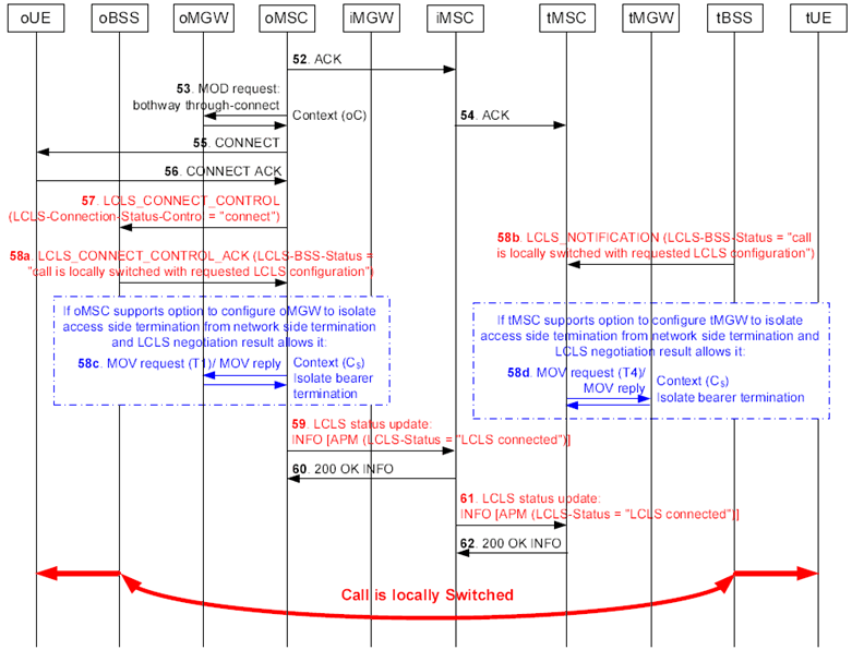
Figure 6.3.4.4: Basic Call Establishment when call is locally switched (continuation of Figure 6.3.4.3)
(⇒ copy of original 3GPP image)
(⇒ copy of original 3GPP image)
Step 52.
The oMSC server replies to the succeeding node with the ACK request to confirm the reception of the 200 OK final response.
Step 53.
The oMSC server request the oMGW to bothway through-connect the bearer.
Step 54.
The iMSC server transfers the ACK request to the succeeding node.
Step 55.
The oMSC server reports Answer/Connect to the oUE.
Step 56.
The oUE returns the CONNECT ACKNOWLEDGE message to the oMSC server.
Step 57.
The oMSC server requests the oBSS to connect LCLS since the received 200 OK (INVITE) final response indicated "LCLS is feasible but not yet connected".
Step 58.
-
Step 59.
- Since the BSS has received the through connect request for both call legs the oBSS returns the LCLS_CONNECT_CONTROL_ACK message with the LCLS-BSS-Status IE set to "call is locally switched with requested LCLS configuration".
- The tBSS signals the LCLS status change to the tMSC server by sending the LCLS_NOTIFICATION message with the LCLS-BSS-Status IE set to "call is locally switched with requested LCLS configuration".
- If the oMSC server supports the option to configure its Access MGW to isolate the access side termination from the network side termination and LCLS negotiation indicated that no succeeding node requires the UL data from the oUE then the oMSC server requests the oMGW to isolate the access side termination T1 from the network side termination T2.
- If the tMSC server supports the option to configure its Access MGW to isolate the access side termination from the network side termination and LCLS negotiation indicated that no preceding node requires the UL data from the tUE then the tMSC server requests the tMGW to isolate the access side termination T4 from the network side termination T3.
The oMSC server signals the change of the LCLS status through the Core Network by sending the INFO request with the encapsulated APM message with the LCLS-Status IE set to "LCLS connected".
Step 60.
The iMSC server returns the 200 OK (INFO) final response to the preceding node.
Step 61.
The iMSC server transfers the change of the LCLS status to the succeeding node.
Step 62.
The tMSC server returns the 200 OK (INFO) final response to the preceding node.