Content for TS 23.284 Word version: 17.0.0
1…
4…
4.2…
4.3…
5
6…
6.3…
6.3.2
6.3.3
6.3.4
6.3.5
7…
7.2.4…
7.2.4.2
7.2.4.3
7.2.4.4
7.2.4.5
7.2.4.6
7.3…
7.3.4…
7.3.4.2
7.3.4.3
7.3.4.4
8…
8.2.3
8.3…
8.3.2
8.4…
8.4.1.1.7…
8.4.1.2…
8.4.2…
8.4.2.2…
8.4.5…
8.4.5.6
8.4.5.7
8.4.5.8…
9…
13…
13.4…
13.4.3…
13.4.4…
13.5…
13.6…
13.7…
14…
16…
A…
A.2…
13.5 Call Waiting (CW)
13.5.1 Principles
13.5.2 Accept the new incoming call, the original call is hold
13.5.2.1 General
13.5.2.2 Example
13.5.2.2.1 Connection Model
13.5.2.2.2 Basic Sequence
...
...
13.5 Call Waiting (CW) p. 151
13.5.1 Principles p. 151
The procedures specified for the Call Waiting supplementary service in TS 23.205, clause 13.6 for BICC based CS Core Network and in TS 23.231 clause 13.6 for SIP-I based CS Core Network shall be followed with the following modifications:
The call establishment and call clearing procedures defined in clauses 6 and 7 shall be applied.
If the new call is accepted, the GCR of the new call is sent to the BSS in the ASSIGNMENT procedure
The following clauses describe the additional requirements related to the LCLS functionality when the Call Waiting supplementary service is activated for the locally switched call.
13.5.2 Accept the new incoming call, the original call is hold p. 151
13.5.2.1 General p. 151
When new call arrives and is accepted, the GCR and LCLS-Configuration of the local access bearer shall be modified according to the new call. The MSC Server shall initiate an ASSIGNMENT REQUEST message towards the BSS including the GCR and LCLS-Configuration of the new call.
13.5.2.2 Example p. 152
13.5.2.2.1 Connection Model p. 152
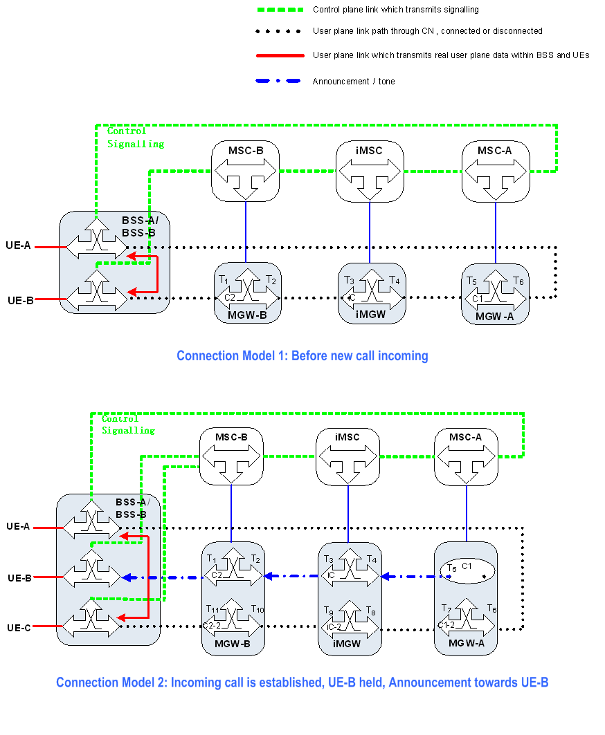
Figure 13.5.2.2.1.1 shows the network model for Call Waiting supplementary service of holding the original call to accept the new call. Termination T1 to T6 is established for original call between UE-A and UE-B. When UE-A and UE-B have an active call established, UE-C, which is roaming under BSS-B and MSC-B, initiates a new call towards UE-A. To accept the new call, UE-A holds the call with UE-B and relocates its access bearer for the new call.
After the new call between UE-C and UE-A is established, a new context (C1-2) is seized in MGW-A. The access bearer termination T6 is moved from C1 to C1-2 and a new network bearer towards the iMGW is created (T7). In the iMGW, a new context (iC-2) is created with terminations for the bearers with MGW-A (T8) and with MGW-B (T9). In MGW-B, new terminations are created for the access bearer towards UE-C (T11) and for bearer towards iMGW (T10).

Figure 13.5.2.2.1.1: Connection Model for Accept Incoming call, original call is held
(⇒ copy of original 3GPP image)
(⇒ copy of original 3GPP image)
13.5.2.2.2 Basic Sequence p. 153
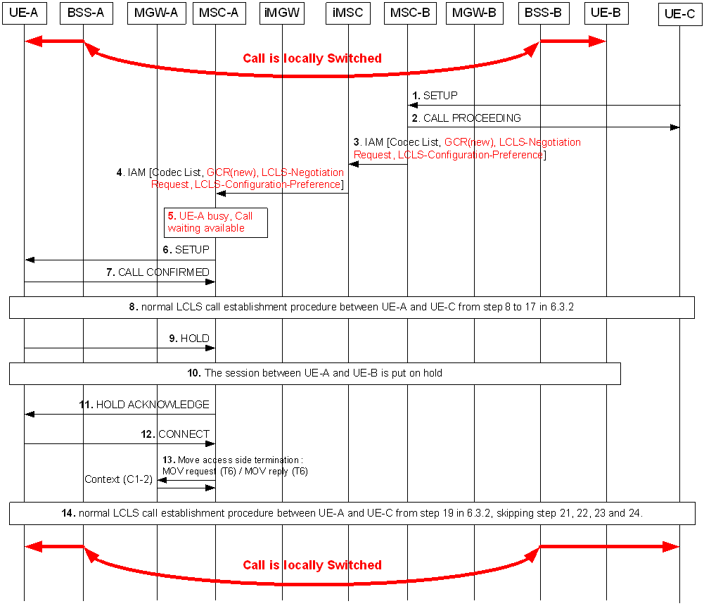
Figure 13.5.2.2.2.1 shows the message sequence example for the acceptance of new call and hold the original one. The ASSIGNMENT REQUEST message is sent from MSC-A to BSS-A to update the GCR stored within the BSS-A.

Step 1.
UE-C sends a SETUP message to the Core Network.
Step 2.
MSC-B responds with CALL PROCEEDING message.
Step 3.
MSC-B sends the IAM message including supported codecs list, GCR with encapsulated BSS-B ID, LCLS-Negotiation Request IE and the LCLS-Configuration-Preference IE.
Step 4.
iMSC transfers the IAM message to MSC-A.
Step 5.
MSC-A determines that UE-A is busy and that call waiting is available.
Step 6.
MSC-A sends a SETUP message to UE-A.
Step 7.
UE-A responds with CALL CONFIRM message.
Step 8.
The normal LCLS call establishment procedures from step 8 to 17 in clause 6.3.2 are applied.
Step 9.
UE-A requests to hold the call with UE-B.
Step 10.
The session between UE-A and UE-B is put on hold. The procedure in clause 13.6.2.3.2 is applied.
Step 11.
After the session between UE-A and UE-B is put on hold, MSC-A sends the acknowledgement to UE-A.
Step 12.
UE-A accepts the incoming call by sending CONNECT message to MSC-A.
Step 13.
MSC-A requests the MGW to move the termination T6 to the context of incoming call (C1-2).
Step 14.
The normal LCLS call establishment procedures from step 19 in clause 6.3.2 are applied, skipping step 21, 22 a, 22b, 23 and 24. BSS-A shall update the GCR and the LCLS-Configuration on receipt of the ASSIGNMENT REQUEST message for the access bearer.