Content for TS 23.284 Word version: 17.0.0
1…
4…
4.2…
4.3…
5
6…
6.3…
6.3.2
6.3.3
6.3.4
6.3.5
7…
7.2.4…
7.2.4.2
7.2.4.3
7.2.4.4
7.2.4.5
7.2.4.6
7.3…
7.3.4…
7.3.4.2
7.3.4.3
7.3.4.4
8…
8.2.3
8.3…
8.3.2
8.4…
8.4.1.1.7…
8.4.1.2…
8.4.2…
8.4.2.2…
8.4.5…
8.4.5.6
8.4.5.7
8.4.5.8…
9…
13…
13.4…
13.4.3…
13.4.4…
13.5…
13.6…
13.7…
14…
16…
A…
A.2…
7.3.4.2 MSC server Initiated Example Call Flow p. 60
Figure 7.3.4.2.1 shows the message sequence example for the MSC server initiated LCLS Re-establishment. In the example the MSC server trigger the LCLS negotiation in the CN. The BSS establishes local switching when both legs are informed LCLS is allowed.
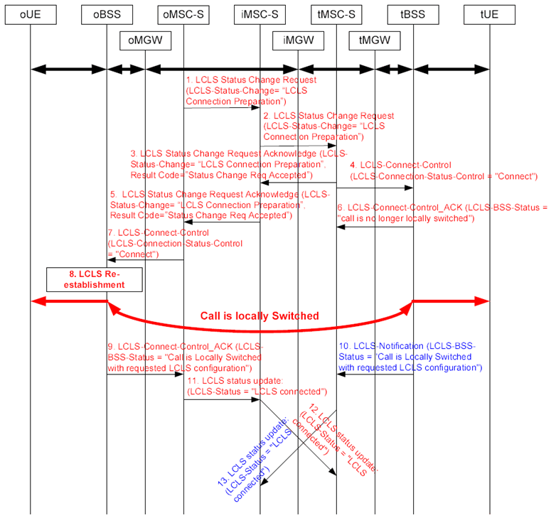
Step 1.
The oMSC server determines that local switching should be re-established. The oMSC server sends to the succeeding node the LCLS Status Change Request message with the LCLS-Status-Change IE set to "LCLS-Connection-Preparation".
Step 2.
The iMSC server transfers the LCLS Status Change Request message to the tMSC server.
Step 3.
The tMSC server sends LCLS Status Change Request Acknowledge message to the preceding node.
Step 4.
The tMSC server sends to the tBSS the LCLS-Connect-Control message with the LCLS-Connection-Status-Control IE set to "connect".
Step 5.
The iMSC server transfers the LCLS Status Change Request Acknowledge message to the oMSC server.
Step 6.
The oBSS confirms the reception of the LCLS connect request but does not change the LCLS-BSS status since LCLS connect request is not yet received for the associated call leg.
Step 7.
On receipt of LCLS Status Change Request Acknowledge message, the oMSC server sends to the oBSS the LCLS-Connect-Control message with the LCLS-Connection-Status-Control IE set to "connect".
Step 8.
Because LCLS connect requests are received for the associated call leg, the oBSS/tBSS re-establish the LCLS.
Step 9.
The oBSS reports the LCLS connection by sending the LCLS-Connect-Control Acknowledge message to the oMSC server.
Step 10.
The tBSS reports the LCLS connection by sending the LCLS-Notification message to the tMSC server.
Step 11.
The oMSC server sends the LCLS Status Update message with the LCLS-Status IE set to "LCLS Connected" to the succeeding node.
Step 12.
The iMSC server transfers the LCLS Status Update message to the tMSC server.
Step 13.
The tMSC server sends the LCLS Status Update message with the LCLS-Status IE set to "LCLS Connected" to the preceding node. The iMSC server does not forward the LCLS Status Update message to the oMSC server since the same LCLS Status is already received from the oMSC server.
![]()
![]()
![]()