Content for TS 23.284 Word version: 17.0.0
1…
4…
4.2…
4.3…
5
6…
6.3…
6.3.2
6.3.3
6.3.4
6.3.5
7…
7.2.4…
7.2.4.2
7.2.4.3
7.2.4.4
7.2.4.5
7.2.4.6
7.3…
7.3.4…
7.3.4.2
7.3.4.3
7.3.4.4
8…
8.2.3
8.3…
8.3.2
8.4…
8.4.1.1.7…
8.4.1.2…
8.4.2…
8.4.2.2…
8.4.5…
8.4.5.6
8.4.5.7
8.4.5.8…
9…
13…
13.4…
13.4.3…
13.4.4…
13.5…
13.6…
13.7…
14…
16…
A…
A.2…
8.3.2 Inter-MSC GSM to UMTS Relocation p. 83
8.3.2.1 General p. 83
When a call is locally switched through the BSS and an inter-MSC GSM to UMTS handover occurs the LCLS shall be broken and the user plane shall be connected through the core network. The Inter-MSC GSM to UMTS handover procedures specified in TS 23.009, TS 23.205 and TS 23.231 shall be followed. The following clauses describe the additional requirements for inter-MSC GSM to UMTS handovers of LCLS related calls.
8.3.2.2 MSC-1 / MGW-1 p. 83
8.3.2.2.1 Handover Required p. 83
When MSC-1 Server receives the Handover Required message from the serving BSS and determines that the call shall be handed over to the Target MSC Server, it shall send the GCR of the call, the LCLS-Negotiation Request IE and the LCLS-Configuration-Preference IE to the Target MSC Server in a MAP Prepare-Handover_Request message.
8.3.2.2.2 Iu Relocation Request Acknowledge p. 83
Upon receipt of the MAP Prepare-Handover-Response including Iu Relocation Ack message, the MSC-1 Server shall send to the adjacent call node the LCLS-Status-Change-Request message to indicate "LCLS Disconnection-Preparation-for handover".
If the far end MSC server receives the LCLS-Status-Change-Request message indicating LCLS Disconnection preparation-for-handover it shall send to the BSS the LCLS_Connect_Control message with the LCLS-Connection-Status-Control IE indicating "BicastatHandover". When the LCLS_Connect_Control acknowledge message is received from the BSS, the far end MSC server shall return the LCLS Status Change Request Acknowledge message indicating "LCLS Disconnection-Preparation-for-handover" and a Result code indicating LCLS Status Change Request accepted.
8.3.2.2.3 Bearer establishment between MGW-1 and Target MGW p. 83
The handling of the bearer establishment between MGW-1 and Target MGW is as described in clause 6.1 for a Basic Mobile Originating Call. The MSC server shall also use the Change Flow Direction procedure to request the MGW-1 to set the Handover Device to the initial state.
8.3.2.2.4 MGW Flow Direction Control p. 83
The MSC Server may perform the MGW Flow Direction Control for GSM to UMTS Relocation as described in clause 8.4.2.1.2.4.
8.3.2.2.5 Handover Command/Iu Relocation Detect p. 83
When the MSC-1 server sends the Handover Command message or alternatively, if it receives the Iu Relocation detect message inside a MAP Process-Access-Signalling request, the MSC-1 server shall follow the procedures described in clause 8.4.2.1.2.5.
8.3.2.2.6 Iu Relocation Complete p. 83
When the MSC-1 server receives the Iu Relocation Complete message inside a MAP Send-End-Signalling Request and an ANSWER message including the LCLS status set to LCLS disconnected, it releases the A-interface line towards the serving BSS. The MSC-1 server also requests the MGW-1 to set the Handover Device to its final state by removing the bearer termination (TS) towards the serving BSS.
The MSC-1 server shall send to the adjacent call node the LCLS-Status-Update message with the LCLS-Status IE indicating the LCLS is disconnected.
When the serving BSS receives Clear Command it shall release any local switch path. The serving BSS shall inform the far end MSC server that LCLS is broken with the LCLS-Notification message.
8.3.2.3 Target MSC Server / Target MGW p. 84
8.3.2.3.1 Prepare Handover Request message and MGW selection p. 84
The Target MSC server selects the Target MGW when it receives Prepare Handover Request message. The Target MSC server sends the Iu Relocation Request message to the Target RNC as for the normal case.
8.3.2.3.2 Bearer establishment towards Target RNC p. 84
The procedure specified in TS 23.205, clause 8.3.2.2 shall be used.
8.3.2.3.3 Bearer establishment between MGW-1 and Target MGW p. 84
The handling of the bearer establishment between MGW-1 and Target MGW is as described for basic mobile terminating call in clause 6.2.
8.3.2.4 Example of Inter-MSC GSM to UMTS Relocation p. 84
8.3.2.4.1 Connection Model p. 84
Figure 8.4.2.1.4.1.1 shows the network model for the Inter-MSC GSM to GSM Handover, where call leg UE-1 is handed over from BSS-1 to the Target RNC. BSS-1 is the same as BSS-2 when LCLS is established for the call. The BSS-1 is served by the MSC-Server 1, the Target RNC is served by the Target MSC-Server, and MSC-Server 1 is not the same as Target MSC-Server. The bearer termination T2 in MGW-2 is used for the bearer towards BSS-2, which is not affected by this handover. Bearer termination TS in MGW-1 is used for the bearer towards BSS-1 and the bearer terminations TA and T3 in MGW-1, T1 in MGW-2 and T4 in Target-MGW are used for the bearer towards the succeeding/preceding MGW. Bearer termination TT in Target-MGW is for the bearer termination towards the Target RNC.
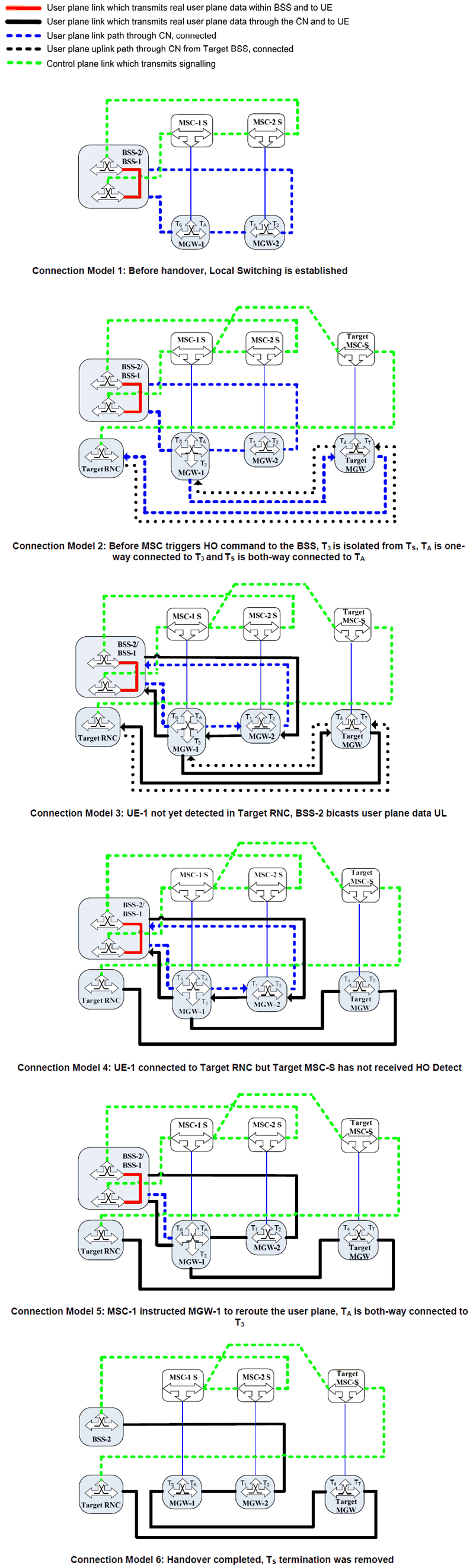
Figure 8.3.2.4.1.1: Inter-MSC GSM to UMTS Relocation Connection Model when user plane active
(⇒ copy of original 3GPP image)
(⇒ copy of original 3GPP image)
8.3.2.4.2 Basic Sequence for Inter-MSC handover that breaks Local Switching p. 87
Figure 8.3.2.4.2.1 and Figure 8.3.2.4.2.2 show the message sequence example for the basic Inter-MSC GSM to GSM Handover shown in the corresponding network model Figure 8.3.2.4.1.1. The Handover Device is located in the MGW-1 selected for the call establishment by the MSC-1 Server, which controls the call and the mobility management. The description is based on TS 23.009, TS 23.205 and TS 23.231.
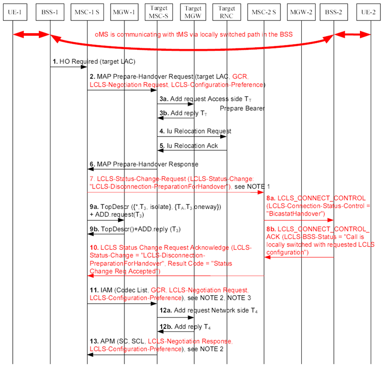
Figure 8.3.2.4.2.1: Inter-MSC GSM to UMTS Relocation that breaks Local Switching when user plane active, initial phase
(⇒ copy of original 3GPP image)
(⇒ copy of original 3GPP image)
Step 1.
The Handover Required message is received from BSS-1 requesting an inter-MSC GSM to UMTS handover. The call is currently locally switched and the MSC-1 server knows that the Inter-MSC GSM to UMTS relocation at one end will break LCLS (the local switch is not broken in the serving BSS (BSS-1) until UE-1 has moved out of the BSS-1 and the MSC-1 server sends the Clear Command message to BSS-1).
Step 2.
The MSC-1 Server determines that inter-MSC handover is required and sends MAP-Prepare-Handover Request message to target MSC which includes GCR, the LCLS Negotiation Request IE and the LCLS-Configuration-Preference IE.
Step 3a, b.
The Target MSC-Server requests Target MGW to provide a binding reference and a bearer address using the Prepare Bearer procedure when reserving TT towards the Target RNC.
Step 4.
The Target MSC-Server sends the Iu Relocation Request message to Target RNC.
Step 5.
The Target RNC sends the Iu Relocation Acknowledge message to Target MSC-Server.
Step 6.
The Target MSC-Server sends the Prepare Handover Response message to the MSC-1 server.
Step 7.
The Anchor MSC-1 server may instruct the far end MSC-2 server to prepare for LCLS disconnection due to handover by sending the LCLS-Status-Change-Request message. (If the Anchor MSC-1 server does not instruct the MSC-2 server /BSS-2 to prepare for LCLS disconnection for handover, BSS-2 starts bicasting user plane data to the core network after receiving the Handover Command message in Step 15.)
Step 8a.
The far end MSC-2 server requests BSS-2 to start sending data UL with the LCLS_Connect_Control message and the LCLS-Connection-Status-Control IE indicating "BicastatHandover", see Figure 8.3.2.4.1.1, Connection Model 3. This triggers the BSS-2 to bicast the user plane data in the same way as the Access MGW-1 would be doing in a non-LCLS inter-BSS handover. At this point the BSS-1 shall send any DL data it receives directly to the served UE.
Step 8b.
The BSS-2 sends the LCLS_Connect_Control_Ack message with the LCLS-BSS-Status IE set to "the call is locally switched with requested LCLS configuration".
Step 9a, b.
In accordance with normal Iu relocation in this example the MSC-1 server requests MGW-1 to isolate the termination towards Target MGW (T3) from the termination to the Serving BSS-1 (TS) and to configure the Anchor termination (TA) one-way DL towards the Target MGW termination (T3).
Step 10.
MSC-2 Server sends LCLS-Status-Change-Request-Acknowledge message.
Step 11.
MSC-1 Server sends IAM (Initial Address Message) to Target MSC-Server including GCR, the LCLS-Negotiation Request IE and the LCLS-Configuration-Preference IE.
Step 12a, b.
Target-MSC-Server reserves bearer connection T4 towards MGW-1.
Step 13.
After Target MGW has replied with the bearer address and the binding reference, Target MSC-Server returns APM with selected codec and LCLS-Negotiation Response IE and the LCLS-Configuration-Preference IE.
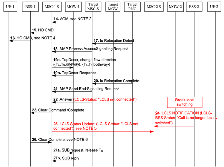
Figure 8.3.2.4.2.2: Inter-MSC GSM to UMTS Relocation that breaks Local Switching when user plane active, completion phase
(⇒ copy of original 3GPP image)
(⇒ copy of original 3GPP image)
Step 14.
The Target MSC-Server sends ACM (Address Complete Message). Target MSC-Server awaits the capturing of the UE-1 on the radio path when the ACM is sent and the Anchor MSC-1 server initiates the Iu relocation execution when receiving ACM.
Step 15.
MSC-1 server sends Handover Command message to BSS-1.
Step 16.
BSS-1 sends Handover Command message to UE-1. BSS-1 will discard incoming user plane data send to UE-1 received from CN. If BSS-2 was not instructed to prepare for LCLS related handover in Step 8a, the BSS-2 starts bi-casting UP user plane data generated by UE-2 to local path and A interface and also starts to check whether there is incoming DL user plane data from the core network.
Step 17.
UE-1 is detected at Target RNC. But still no UL data can be sent from Target RNC to MGW-1 because TA-T3 is one-way DL only. MGW-1 will continue to transmit DL user plane data to the Target RNC. BSS-2 continues to bi-cast user plane data to both local path and to the A interface.
Step 18.
Target MSC-Server sends MAP-Process-Access-Signal request message to the MSC-1 server.
Step 19a, b.
The MSC-1 server uses the Change Flow Direction procedure to request the MGW-1 to set the Handover Device to intermediate state and TA-T3 to both-way configuration. When BSS-2 finds out there is DL user plane data, BSS-2 will transmit the DL user plane data to UE-2.
Step 20.
Iu Relocation Complete message is received from Target RNC with LCLS-BSS-status indicating that the call cannot be locally switched.
Step 21.
Iu-Relocation-Complete message when received is included in the MAP SendEndSignalling Request message sent to the MSC-1 server.
Step 22.
Target MSC-Server sends ANSWER with the LCLS-status when Iu-Relocation Complete message is received.
Step 23.
MSC-1 server informs BSS-1 to clear the old call leg.
Step 24.
Serving BSS-2 informs MSC-2 server that LCLS is broken via LCLS-Notification message.
Step 25.
MSC-1 server sends LCLS Status Update message with LCLS status "LCLS not connected" to MSC-2 server.
Step 26.
BSS-1 informs MSC-1 server that the resource for the UE-1 has been released and BSS-2 stops bi-casting.
Step 27a, b.
The MSC-1 server requests MGW-1 to set the Handover Device to its final state by removing the bearer termination TS towards BSC-1 using the Release Termination procedure.
![]()
![]()
![]()