Content for TS 23.203 Word version: 18.0.0
0…
4…
5…
6…
6.1.4…
6.1.7…
6.1.10…
6.1.17…
6.2…
6.2.2…
6.2.3…
6.3
6.4…
6.8…
7…
7.3…
7.4…
7.7…
7.7.3…
7.8…
A…
A.4…
D…
P…
P.4.2.4…
P.7…
P.7.5…
P.8
Q…
S…
S.7…
S.8.8
T…
D Access specific aspects (Non-3GPP)
D.1 DOCSIS IP CAN
D.1.0 General
D.1.1 High level requirements
D.1.2 Architecture model and reference points
D.1.3 Functional description
D.2 WiMAX IP CAN
D.2.1 High level requirements
D.2.2 Architecture model and reference points
D.2.3 Functional description
G PCC rule precedence configuration
H Access specific aspects (EPC-based Non-3GPP)
J Standardized QCI characteristics - rationale and principles
K Limited PCC Deployment
L Limited PCC Deployment
M Handling of UE or network responsibility for the resource management of services
N PCC usage for sponsored data connectivity
...
...
D Access specific aspects (Non-3GPP) p. 193
D.1 DOCSIS IP CAN p. 193
D.1.0 General p. 193
D.1.1 High level requirements p. 193
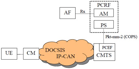
In the DOCSIS IP-CAN, each UE is connected to the network via a Cable Modem (CM) which is connected through a Hybrid Fibre Coax (HFC) access network to a Cable Modem Termination System (CMTS). Though the UE and CM may or may not be embedded within the same physical package, they remain separate logical devices. One or more UEs may subtend a single CM. Because the CMTS provides the IP connectivity and traffic scheduling and manages quality of service for the CM and the UEs which subtend it, the CMTS fulfils the role of PCEF for the DOCSIS IP-CAN. In the DOCSIS IP-CAN, the Application Manager (AM) and the Policy Server (PS) fulfil the role of the PCRF.
When accessing resources via a DOCSIS IP-CAN, the Rx interface can be used to request resources. The communication between the AM and PS and the PS and CMTS uses the PKT-MM-2 interface which is based on COPS and defined in J.179. The remainder of this clause documents the mapping of PCC terminology to the DOCSIS IP-CAN and how the DOCSIS IP-CAN realizes the defined PCC functionality. This clause also establishes the requirements of the Rx interface as it is used for the DOCSIS IP-CAN.
The PKT-MM-2 interface is shown here for information to illustrate the organization of the DOCSIS IP-CAN. References that specify the PKT-MM-2 interface do not constitute normative requirements for the 3GPP architecture. The DOCSIS IP-CAN does not intend to pose any new normative requirements for the Gx interface.
D.1.1.1 General p. 193
The DOCSIS IP-CAN employs for an IP-CAN session, the concept of a DOCSIS registration.
The DOCSIS IP-CAN employs for an IP-CAN bearer, the concept of a DOCSIS service flow in order to provide an information path between the UE and the CMTS. Note that DOCSIS service flows are unidirectional, either upstream (toward the CMTS) or downstream (toward the CM). When a CM is registered in the DOCSIS IP-CAN, it is assigned a unique IP Address and separate primary service flows are created for both the upstream and downstream direction These primary service flows are typically given best effort scheduling and are used to carry all IP traffic through the CM for which a more specific service flow has not been created. When a UE is registered in the DOCSIS IP-CAN, it is assigned its own IP Address and is identified by its MAC address. A UE does not have a service flow assigned to it as a result of registration; rather it is associated with the primary service flows of the CM through which it is attached to the network. Additional bearers for the UE are created dynamically as required to provide appropriate QoS for service flows.
Bearer creation is triggered when media descriptors (Media Type and Format) for the SIP session are sent from the AF to the AM over the Rx interface. The AM translates the media descriptors into a QoS request for a DOCSIS service flow. The AM then forwards the QoS request towards the bearer enforcement point using the PKT-MM-2 interface. The PKT-MM-2 interface is not a 3GPP reference point, Specifications that detail the PKT-MM-2 interface do not impose normative requirements on the 3GPP architecture.
The following Figure provides a graphical representation of the DOCSIS IP-CAN and how it maps into the generic PCC terminology.
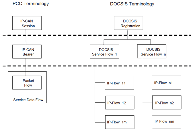
The DOCSIS IP-CAN defines an IP-Flow to be a unidirectional sequence of packets identified by OSI Layer 3 and Layer 4 header information. This information includes source/destination IP addresses, source/destination port numbers, protocol ID. Multiple Multimedia streams may be carried in a single IP Flow.
In a DOCSIS IP-CAN, there is no equivalent concept as a service data flow. Further a DOCSIS service flow is uni-directional and each service flow is an aggregation of the QoS needs for all the IP-Flows which make up the service flow. As such, the QoS enforcement is done at the service flow level not at the IP-Flow level.
D.1.1.2 Charging related requirements p. 194
Void
D.1.1.3 Policy control requirements p. 194
Void
D.1.2 Architecture model and reference points p. 195
D.1.2.1 Reference points p. 195
D.1.3 Functional description p. 195
D.1.3.1 Overall description p. 195
The DOSCIS IP-CAN employs for an IP-CAN bearer, the concept of a DOCSIS service flow in order to provide an information path between the UE and the CMTS. When a Cable Modem is registered in the DOCSIS IP-CAN, primary upstream and downstream service flows are created.
When a UE is registered in the DOCSIS IP-CAN it is associated with the primary service flows of the cable modem through which it is attached to the network. Based on session information provided by the AF using the Rx reference point, the Application Manager will determine QoS requirements for each IP flow. IP flows which do not require special quality of service treatment may be carried over the primary service flows. For other IP flows which require specific QoS treatment, the Policy Server requests the CMTS to admit the flows using the pkt-mm-2 interface providing detailed information of the QoS requirements. Provided that resources are available, the CMTS will create additional bearers dynamically and push the appropriate traffic filters to the cable modem.
D.1.3.1.1 Binding mechanism p. 195
In the DOCSIS IP-CAN, the binding mechanism is achieved through the use of traffic Classifiers. These Classifiers filter traffic destined to a UE behind a Cable Modem or sourced from a UE behind a Cable Modem, to a particular DOCSIS service flow. DOCSIS Classifiers contain the following attributes which can be used to filter IP traffic:
- IP Type of Service - Range and Mask;
- IP Protocol;
- IP Source Address;
- IP Source Mask;
- IP Destination Address;
- IP Destination Mask;
- TCP/UDP Source Port Start;
- TCP/UDP Source Port End;
- TCP/UDP Destination Port Start;
- TCP/UDP Destination Port End.
D.1.3.2 Functional entities p. 196
D.1.3.2.1 Policy Control and Charging Rules Function (PCRF) p. 196
In the DOCSIS IP-CAN, the Application Manager (AM) and the Policy Server (PS) fulfil the role of the PCRF.
The AM receives media descriptors (Media Type and Format) from the AF for SIP sessions and maps the QoS needs of the session to a FlowSpec, The FlowSpec is a layer 2 independent representation of the bandwidth and QoS requirements for the flow derived from the media descriptors using a well defined algorithm. The AM and PS provide network resource control in the DOCSIS IP-CAN by managing the CMTS using the PacketCable Multimedia interface pkt-mm-2.
The AM and PS map IP flows to DOCSIS service flows in accordance with the operator's policies and based on the media format information provided by the AF.
D.1.3.2.1.1 Input for PCC decisions p. 196
The AM accepts any of the following input as a basis for decisions on PCC rule operations:
- Per IP-CAN session (e.g.: UE IP address);
- Requested QoS, media format, priority indicator.
- Subscribers maximum allowed QoS resources.
D.1.3.2.2 Policy and Charging Enforcement Function (PCEF) p. 196
The CMTS provides PCEF equivalent functionality within the DOCSIS IP-CAN. The CMTS creates, modifies, and deletes DOCSIS service flows upon request of the Policy Server. The CMTS receives requests from the Policy Server over the pkt-mm-2 interface.
D.1.3.2.3 Application Function (AF) p. 196
Void
D.1.3.3 Policy and charging control rule p. 196
D.2 WiMAX IP CAN p. 197
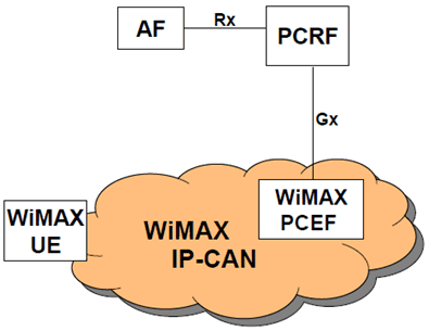
In the WiMAX IP-CAN, the UE (also referenced as Mobile Station or MS in IEEE 802.16 standards) connects to the WiMAX Access Service Network (ASN). The ASN logically communicates with a Connectivity Service Network (CSN) which is a collection of core networking functions (e.g. Mobile IP HA, AAA Server, DHCP, DNS etc.). The ASN manages traffic admission and scheduling, enforces QoS for an authorized UE and performs accounting functions for the UE (per session, flow, or UE). WiMAX PCEF is part of WiMAX IP-CAN and is to be defined by WiMAX Forum [15]. WiMAX PCEF terminates the Gx reference point from the PCRF and may be a distributed enforcement architecture.
The PCC functional mapping to WiMAX IP-CAN is shown in the following Figure where PCC Gx and Rx are applied.
D.2.1 High level requirements p. 197
D.2.1.1 General p. 197
No new requirements have been identified.
D.2.1.2 Charging related requirements p. 197
No new requirements have been identified.
D.2.1.3 Policy control requirements p. 197
No new requirements have been identified.
D.2.2 Architecture model and reference points p. 198
D.2.2.1 Reference points p. 198
D.2.2.1.1 Rx reference point p. 198
WiMAX IP-CAN imposes no new requirements to the Rx reference point.
D.2.2.1.2 Gx reference point p. 198
WiMAX IP-CAN imposes no new requirements to the Gx reference point other than WiMAX specific values for existing Gx parameters (e.g. RAT type) as described in [15].
D.2.2.1.3 Sp reference point p. 198
WiMAX IP-CAN imposes no new requirements to the Sp reference point.
D.2.3 Functional description p. 198
D.2.3.1 Overall description p. 198
The WiMAX IP-CAN employs for an IP-CAN bearer, the concept of a WiMAX service flow, in order to provide a data path between the UE and the WiMAX CSN via the ASN. When a UE is registered in the WiMAX IP-CAN, it is associated with one or more WiMAX service flows. Based on session information provided by the AF via the Rx reference point, the PCRF determines the QoS requirements for each service by constructing PCC rules. The PCRF requests the WiMAX IP-CAN via Gx interface to enforce the authorized PCC rules on the WiMAX service flows. The PCEF function in the WiMAX IP-CAN enforces the PCC rules received from the PCRF. Provided that resources are available, the ASN creates and configures logical bearers and enforces creation of appropriate traffic classes associated with service flows compliant with IEEE 802.16 standards for the air interface and IP-CAN bearer capabilities in the ASN (e.g. DiffServ).
D.2.3.1.1 Binding mechanism p. 198
Void
D.2.3.1.2 Credit management p. 198
Void
D.2.3.1.3 Event triggers p. 198
Void
D.2.3.2 Functional entities p. 198
D.2.3.2.1 Policy Control and Charging Rules Function (PCRF) p. 198
The 3GPP PCRF is used for the WiMAX IP-CAN. The PCRF interacts with WiMAX IP-CAN using 3GPP Gx reference point.
D.2.3.2.2 Policy and Charging Enforcement Function (PCEF) p. 199
For WiMAX IP-CAN, PCEF functions may be distributed. It additionally:
- Terminates the Gx reference point from PCRF and may act as a proxy for the PCRF.
- Handles the enforcement function relocation in WiMAX IP-CAN in a way that is transparent to the PCRF.
D.2.3.2.3 Application Function (AF) p. 199
WiMAX IP-CAN imposes no requirements to the AF functionalities.
D.2.3.3 Policy and charging control rule p. 199
E Void
F Void
G PCC rule precedence configuration p. 202
The precedence information is part of the PCC rule (see clause 6.3.1) and instructs the PCEF in which order the service data flow templates of the active PCC rules needs to be analyzed when an IP packet arrives. This mechanism ensures that the service data flows can be correctly identified even if the service data flow templates contain overlapping service data flow filters.
For PCC rules that contain an application identifier (i.e. that refer to an application detection filter), the order and the details of the detection are implementation specific. Once an application has been detected, enforcement and charging shall however be applied under consideration of the PCC rule precedence, i.e. when multiple PCC rules overlap, only the enforcement and charging actions of the PCC rule with the highest precedence shall be applied.
Within the PCC framework it is possible to use different types of PCC rules for which the service data flow templates may not always be known by the PCRF. Therefore, the PCC rule precedence information needs to be carefully configured to avoid certain situations e.g. a dynamic PCC rule cannot be applied for service data flow detection due to a predefined PCC rule not known to the PCRF with overlapping filter information and a higher precedence.
For example, an operator could structure the value range of the precedence information into separate value ranges (in decreasing order) for the different types of PCC rules as follows:
- dynamic PCC rules;
- predefined PCC rules known to the PCRF;
- predefined PCC rules not known to the PCRF;
- dynamic PCC rules for non-operator controlled services, i.e. those which are generated by the PCRF based on the UE provided traffic mapping information (and which take over the UE provided precedence information).
H (Normative) Access specific aspects (EPC-based Non-3GPP) |R8| p. 203
H.1 General p. 203
An EPC-based non-3GPP IP-CAN (TS 23.402), which requires the Gxa for dynamic QoS control, shall include the BBERF. The allocation of a BBERF to a node within the non-3GPP IP-CAN is out of 3GPP scope, unless otherwise specified in this Annex.
H.2 EPC-based cdma2000 HRPD Access p. 203
In case of EPC-based cdma2000 HRPD access the BBERF is located in the HRPD Serving Gateway (HSGW) defined in 3GPP2 X.S0057 [20].
The HSGW of an EPC-based cdma2000 HRPD access that supports a Gxa interface shall support all the Gxa procedures defined in this specification.
The operator may configure an indicator in HSS which is delivered to the BBERF in HSGW within the Charging Characteristics and used by the BBERF to not establish the Gateway Control Session during the IP-CAN session establishment procedure.
During the pre-registration phase in case of optimised EUTRAN-to-HRPD handovers, the Serving GW and the HSGW are associated with the IP-CAN session(s) of the UE in the PCRF. The HSGW is the non-primary BBERF. For each PDN connection, if the UE has acquired an IPv6 prefix via the 3GPP access, the PCRF (H-PCRF in the home-routed case, V-PCRF in the local-breakout case) shall provide the IPv6 prefix of UE to the HSGW during the Gateway Control Session establishment procedure. In order to allow PCRF to link the new Gateway Control session to a Gx session based on the information received in the Gateway Control session establishment message, it is assumed that there is only a single IP-CAN session per PDN ID and IMSI.
For EPC based cdma2000 HRPD access, the IP-CAN bearer establishment mode for all of the simultaneous IP-CAN sessions between a UE and a PDN shall have the same value.
H.3 EPC-based Trusted WLAN Access with S2a |R11| p. 204
In an EPC-based trusted WLAN Access with S2a, the PCEF is located in the PDN-GW and the BBERF does not apply.
From the network scenarios listed in clause 7.1, the Case 1 (no Gateway Control Session) applies.
Specific event triggers applicable are listed in Table H.3.
| Event/Credit reauthorization trigger | Description | Reported from | Condition for reporting |
|---|---|---|---|
| RAT type change. | The characteristics of the air interface, communicated as the radio access type, have changed. | PCEF | PCRF/OCS |
For an IP-CAN session set-up over a Trusted WLAN Access with S2a:
- at IP-CAN Session Establishment the PCEF provides TWAN location information (TWAN ID and/or UE Time Zone as described in clause 16 of TS 23.402), IP-CAN type , RAT Type, PLMN identifier and an indication that access is trusted to the PCRF (over Gx). The TWAN ID may include the identifier of the operator of the TWAN as defined in clause 16 of TS 23.402. This occurs at step 3 of Figure 7.2-1 (IP-CAN Session Establishment). This information is also provided by the PCEF to the charging entities as described in TS 32.251.
- The Access Network Information Report event trigger defined in clause 6.1.4 applies. The user location information within the Access Network Information reporting contains the TWAN ID and/or UE Time Zone as described in clause 16 of TS 23.402. This information is sent when a bearer over Trusted WLAN access is activated or modified or deactivated and when the IP-CAN session is terminated. When the bearer over Trusted WLAN access is deactivated or the IP-CAN session is terminated the user location information corresponds to the last known UE location. When the IP-CAN session is terminated a TWAN Release Cause (if available) is also provided to the PCRF.
H.4 EPC-based untrusted non-3GPP Access |R13| p. 204
In an EPC-based untrusted non 3GPP Access, the BBERF does not apply.
Specific event triggers and credit reauthorization triggers are listed in Table H.4.
| Event/Credit reauthorization trigger | Description | Reported from | Condition for reporting |
|---|---|---|---|
| RAT type change. | The characteristics of the air interface, communicated as the radio access type, have changed. | PCEF | PCRF/OCS |
For an IP-CAN session set-up over an untrusted non-3GPP access over S2b:
-
At IP-CAN Session Establishment the PCEF provides IP-CAN type, indication that it is untrusted RAT type, ePDG IP address and the Serving Network Identifier to the PCRF. This occurs at step 3 of Figure 7.2-1 (IP-CAN Session Establishment). This information is also provided by the PCEF to the charging entities as described in TS 32.251. The PCEF provides also the PCRF with User location information it may have received from the ePDG. As defined in TS 23.402, this User location information may contain: ePDG IP address used in IKEv2 tunnel procedures. The local IP address and the UDP or TCP port number (if NAT was detected) detected by the ePDG as the source of the UE traffic over Swu.
- WLAN Location Information and the WLAN Location Information Age. The TWAN ID within the WLAN location Information includes the identifier of the operator of the TWAN as defined in clause 16 of TS 23.402.
- The IP-CAN type changes, the PLMN change event trigger defined in clause 6.1.4 and RAT type changes event trigger applies. The PCEF reports to PCRF when a Create Session Request is received including information that the UE moved to an untrusted WLAN access. This information is also provided by the PCEF to the charging entities as described in TS 32.251. As described for the case of an IP-CAN Session Establishment, the PCEF provides also the PCRF with location information it may have received from the ePDG and the ePDG IP address used in IKEv2 tunnel procedures.
- When the PCRF subscribes to any of the listed above event triggers using the Provision of PCC Rules procedure, the PCEF provides the parameter values in the response back to the PCRF, as defined in clause 6.1.4.
-
The Access Network Information Report event trigger defined in clause 6.1.4 applies. As defined in TS 23.402, the user location information within the Access Network Information reporting may contain:
- The local IP address and the UDP or TCP port number (if NAT was detected) detected by the ePDG as the source of the UE traffic over Swu.
- WLAN Location Information and the WLAN Location Information Age.
-
When the IP-CAN session is terminated a UWAN Release Cause (if available) is provided to the PCRF. As defined in TS 23.402, the User Location Information within the Access Network Information reporting may contain:
- The local IP address and the UDP or TCP port number (if NAT was detected) detected by the ePDG as the source of the UE traffic over Swu.
- WLAN Location Information and the WLAN Location Information Age defined in TS 23.402
I Void
J Standardized QCI characteristics - rationale and principles |R8| p. 207
The following bullets capture design rationale and principles with respect to standardized QCI characteristics:
- A key advantage of only signalling a single scalar parameter, the QCI, as a "pointer" to standardized characteristics - as opposed to signalling separate parameters for resource type, priority, delay, and loss - is that this simplifies a node implementation.
- In general, the rate of congestion related packet drops can not be controlled precisely for Non-GBR traffic. This rate is mainly determined by the current Non-GBR traffic load, the UE's current radio channel quality, and the configuration of user plane packet processing functions (e.g. scheduling, queue management, and rate shaping). That is the reason why services using a Non-GBR QCI should be prepared to experience congestion related packet drops and/or per packet delays that may exceed a given PDB. The discarding (dropping) of packets is expected to be controlled by a queue management function, e.g. based on pre-configured dropping thresholds, and is relevant mainly for Non-GBR QCIs. The discarding (dropping) of packets of an SDF aggregate mapped to a GBR QCI should be considered to be an exception as long as the source sends at a rate smaller than or equal to the SDF aggregate's GBR. Under these exceptional conditions, when required by operator policy, the eNodeB can be configured to also use the bearer's ARP priority level to assess the relative priority of packets belonging to different SDFs in determining whether to discard a packet or not.
- An operator would choose GBR QCIs for services where the preferred user experience is "service blocking over service dropping", i.e. rather block a service request than risk degraded performance of an already admitted service request. This may be relevant in scenarios where it may not be possible to meet the demand for those services with the dimensioned capacity (e.g. on "new year's eve"). Whether a service is realized based on GBR QCIs or Non-GBR QCIs is therefore an operator policy decision that to a large extent depends on expected traffic load vs. dimensioned capacity. Assuming sufficiently dimensioned capacity any service, both Real Time (RT) and Non Real Time (NRT), can be realized based only on Non-GBR QCIs.
K Limited PCC Deployment |R8| p. 208
Limited support for policy provisioning occurs in certain deployment scenarios.
If PCC is deployed in the HPLMN but not the VPLMN, dynamic policy provisioning only occurs in the home routed roaming cases if no BBERF is employed, or in the non-roaming scenarios.
In roaming scenarios in which the PCC is deployed in the HPLMN but not the VPLMN, and a GW (BBERF) is used:
- limited policy control is possible when the UE moves from the HPLMN to the VPLMN. In the VPLMN, the UE receives only service according to static policies or according to static subscriber policies, defined outside the PCC framework delivered as described in TS 23.402; the dynamically allocated resources associated with specific EPS Bearers no longer apply after this transition.
- If a UE moves from the VPLMN to the HPLMN, dedicated resource establishment procedures are used to dynamically allocate the appropriate resources in the HPLMN for EPS bearers.
- PCC may still be employed to provision rules to the PCEF/TDF for the purpose of charging on the basis of the IP-CAN session.
L (Normative) Limited PCC Deployment |R8| p. 208
In roaming scenarios in which the PCC is deployed in the HPLMN but not the VPLMN, and a GW (BBERF) is used:
- HPCRF and OCS shall detect based on local configuration according to roaming agreements that the event reporting is restricted. The OCS shall not set re/authorization triggers which would require event reporting that can not be generated.
- The H-PCRF shall inform the AF of event triggers that cannot be reported. The H-PCRF shall inform the AF of events that cannot be reported when AF registers event trigger to the H-PCRF. When the H-PCRF detects limited PCC deployment, some event triggers which are dependent upon reporting from the BBERF cannot be reported. The H-PCRF shall inform the AF of events that cannot be reported when the UE is in or after the UE has handed over to an Access Gateway where the BBERF functionality is not deployed.
M Handling of UE or network responsibility for the resource management of services |R8| p. 209
For access networks supporting network initiated resource signalling, the network can take over the responsibility for the resource management for a service. This means the network triggers the request for resources when the service is started or modified and triggers the release of the resources when the service is terminated. The UE remains responsible for starting the service or reacting to an incoming service signalling and needs to decide about how to proceed with the service if the desired resources are not available.
As the network initiated resource signalling cannot always be used due to UE, access network, roaming or other restrictions, the default responsibility for the resource management for a service is given to the UE. However, the UE and the PCRF may be configured on a per service basis to make use of the network responsibility for resource management if the current access network allows this, i.e. if network initiated resource signalling is possible. The UE configuration regarding the responsibility for the resource management of a service might be updated by device management.
Regarding the PCC functionality, the main difference between the UE and the network responsibility for resource management is in the PCRF behaviour. When the UE is responsible, the PCRF waits with the authorization and installation of PCC rules until an appropriate resource request arrives. The main criteria for authorizing a PCC rule is a match of the service data flow filter information with the UE provided traffic mapping information, i.e. the UE desire to run this service on the requested resource. The QoS requested by the UE is then aligned with the authorized QoS for the PCC rules that are associated with the resource request by the PCRF.
When the network is responsible for the resource management, the PCRF authorizes PCC rules immediately, i.e. when the IP-CAN session is established and when new service information is received from the AF. The authorized PCC rules are installed afterwards.
N PCC usage for sponsored data connectivity |R10| p. 210
N.1 General p. 210
With sponsored data connectivity, the Sponsor has a business relationship with the operator and the Sponsor reimburses the operator for the user's data connectivity in order to allow the user access to an associated Application Service Provider's (ASP) services. Alternatively, the user pays for the connectivity with a transaction which is separate from the subscriber's charging. It is assumed the user already has a subscription with the operator.
A possible deployment configuration for sponsored data connectivity in the non roaming case is illustrated in Figure N.1-1. In the roaming case a S9 reference point is present between the H-PCRF and the V-PCRF.
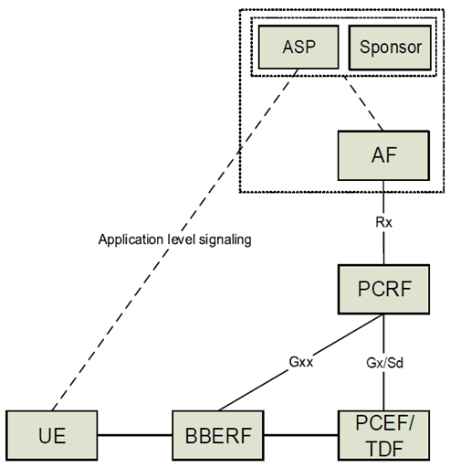
The relationship between the AF and Sponsor and between the Sponsor and ASP is out of scope of this specification. A single AF can serve multiple ASPs and multiple sponsors.
The sponsor may choose to supply the PCRF (via the AF) with the usage thresholds that it expects the PCEF/TDF to enforce. Alternatively, the Sponsor can allow the ASP to enforce such control over the sponsored data connectivity.
The information required for the detection of sponsored HTTP traffic (i.e. server host name) can be verified with the corresponding server IP address/prefix of the IP packets by the PCEF/TDF. The PCEF/TDF uses implementation specific logic to perform this verification.
N.2 Reporting for sponsored data connectivity p. 211
There are two deployment scenarios for usage reporting for sponsored data connectivity. The Sponsor Identifier and Application Service Provider Identifier are provided for sponsored services to the PCRF from the AF over the Rx interface.
In the first scenario the PCRF assigns a service specific Charging Key for a sponsored IP flow. The Charging key is used by the PCEF/TDF to generate separate accounting records for offline charging and and/or usage data records for online charging for the sponsored flows. Correlation of accounting records and usage data records from multiple users per sponsor and/or application service provider is then performed using the charging key.
In a second scenario the Sponsor Identifier and Application Service Provider Identity is included in PCC/ADC rules from the PCRF to the PCEF/TDF as defined in clause 6.3.1. For this scenario the same Charging Key may be used both for IP flows that are sponsored and for flows that are not sponsored. Accounting records generated by the PCEF/TDF for offline charging include the Sponsor Identity and the Application Service Provider Identity. Correlation of accounting records from multiple users per sponsor and/or application service provider can then be based on Sponsor Identity and Application Service Provider Identity instead of the Charging Key. Usage reporting for online charging including Sponsor Identity and Application Service Provider Identity has not been specified in this release of the specification. PCC/ADC rules that include a Sponsor Identity and an Application Service Provider Identity should include a Charging Method that indicates offline charging.
![]()
![]()
![]()