Content for TS 23.203 Word version: 18.0.0
0…
4…
5…
6…
6.1.4…
6.1.7…
6.1.10…
6.1.17…
6.2…
6.2.2…
6.2.3…
6.3
6.4…
6.8…
7…
7.3…
7.4…
7.7…
7.7.3…
7.8…
A…
A.4…
D…
P…
P.4.2.4…
P.7…
P.7.5…
P.8
Q…
S…
S.7…
S.8.8
T…
P.7 PCC Procedures and Flows
P.7.1 Introduction
P.7.2 IP-CAN Session Establishment
P.7.3 IP-CAN Session Termination
P.7.4 IP-CAN Session Modification
...
...
P.7 PCC Procedures and Flows p. 224
P.7.1 Introduction p. 224
From the network scenarios listed in clause 7.1, the Case 1 (no Gateway Control Session over Gxx interface) applies for Fixed Broadband Access for S2a-GTP, S2b-GTP, trusted S2c and H(e)NB scenarios, the Case 2b (a Gateway Control Session over Gxx interface per IP-CAN Session) applies for S2b-PMIP and case 2a (the same Gateway Control Session over Gxx interface for all IP-CAN Sessions) applies for untrusted S2c.
In all information flows, the ePDG is present only in untrusted scenario case 2a and case 2b.
P.7.2 IP-CAN Session Establishment p. 225
P.7.2.0 General p. 225
This procedure is applicable for WLAN and H(e)NB scenarios for EPC routed traffic and for NSWO traffic. This procedure is the same as described in clause 7.2 with the exceptions described in this clause.
P.7.2.1 IP-CAN Session Establishment p. 225
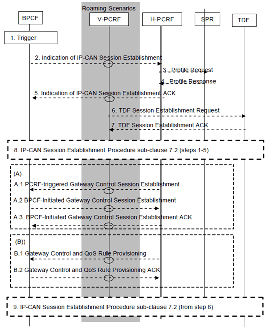
Figure P.7.2.1: IP-CAN Session Establishment for both EPC routed and NSWO traffic
(⇒ copy of original 3GPP image)
(⇒ copy of original 3GPP image)
This procedure is the same as described in clause 7.2 with the additions described below:
Step 1.
The steps from 2 to 7 show PCC signalling to provision PCC rules and ADC rules for NSWO traffic.
The BBF access network may become aware of the IMSI of the 3GPP UE if 3GPP-based access authentication (EAP-AKA/AKA') is performed. The BPCF also becomes aware of the UE local IP address.
Step 2.
The steps from 6 to 10 show PCC signalling to provision policies for EPC routed traffic.
The BPCF Initiates a IP-CAN session establishment over S9a to the PCRF for non-roaming and to the V-PCRF for roaming cases, the information contained in the request message includes IMSI, IP-CAN type, local UE IP address and the NSWO-APN. Triggered by the IP-CAN session establishment over S9 the V-PCRF triggers the S9 session establishment to the H-PCRF.
Step 3-4.
The PCRF retrieves user profile from SPR as described in clause 7.2. As part of the user profile, the PCRF may receive an indication on whether policy control for NSWO traffic should be performed for that UE.
Step 5.
The PCRF enables policy control for NSWO traffic for that UE based on operator policies and user profile information that may depend on e.g. network where the UE is offloading. The PCRF sends a reply message containing PCC Rules if policy control is enabled .
Step 6.
Triggered by the successful establishment of the IP-CAN session for the UE local IP address in step 3, the V-PCRF (roaming) and the PCRF (non-roaming) may establish a session with the TDF to provision ADC Rules for that UE local IP address (if applicable, when solicited application reporting applies and when policy control for offloaded traffic is to be performed). The PCRF provides the TDF with the UE local IP address, the IMSI, the IP-CAN type and the NSWO-APN.
Step 7.
The TDF replies as described in the clause 7.2.
Step 8.
The steps in (A) show PCC signalling to establish a Gateway Control Session over S9a for EPC routed traffic.
IP-CAN session establishment as specified in clause 7.2 is performed, including the establishment of a Gateway Control session (if applicable), as specified below with the following additional information:
In case 2a and case 2b, the ePDG (BBERF) initiates a Gateway Control Session Establishment procedure to provide the UE local IP address and UDP port (if available) as defined in clause P.7.5.1.
For case 1, step 3 of clause 7.2 for WLAN scenario the PCEF includes the UE local IP address and the UDP port number (if available), while for the H(e)NB scenario the PCEF includes the H(e)NB Local IP address and the UDP port number (if available) in the Fixed Broadband Access at which the H(e)NB is connected to.
In case 2b, S-GW (BBERF) initiates a Gateway Control Session Establishment procedure to request QoS Rules for the H(e)NB local IP address as defined in clause P.7.5.1.
The PCRF determines, based on information (UE local IP address information or H(e)NB local IP address information) provided in the IP-CAN session establishment indication or Gateway Control Session establishment indication (if applicable), whether or not the user is connecting via a Fixed Broadband Access Network.
Step A.1.
The steps in (B) show PCC signalling to provision QoS Rules over S9a for EPC routed traffic.
Triggered by the IP-CAN session establishment indication, or triggered by Gateway control session establishment over Gxb*, the PCRF (non-roaming case) or the V-PCRF (visited access roaming case) initiates Gateway Control Session establishment with the BPCF over S9a, if no Gateway Control Session exists for the same IMSI for WLAN scenario. The PCRF includes in the request message to BPCF the IMSI, the UE local IP address and the UDP port number (if available), QoS Rules, and the ePDG IP address (for S2b-GTP access) or PDN GW IP address (for trusted S2c access), while for the H(e)NB scenario, the PCRF (Non-roaming case) or the V-PCRF (visited access roaming case) initiates Gateway Control Session establishment with the BPCF over S9a, if no Gateway Control Session exists for the same H(e)NB including the IMSI, H(e)NB Local IP address, the UDP port number (if available) and QoS Rules. For home routed, the H-PCRF initiates a Gateway Control Session over S9 to trigger the V-PCRF to establish a Gateway Control Session over S9a, for visited access, the V-PCRF initiates a Gateway Control Session over S9 to H-PCRF and the Gateway Control Session over S9a to BPCF.
Step A.2.
For WLAN scenario the BPCF Initiates the Gateway Control session establishment on S9a including in the request message the IMSI, UE Local IP address and the UDP port (if available), while for the H(e)NB scenario it includes the IMSI, H(e)NB Local IP address and the UDP port number (if available) to the PCRF.
Step A.3.
The PCRF reply message contains the result code.
Step B.1.
Triggered by the IP-CAN session establishment indication, or triggered by Gateway control session establishment over Gxb*, the PCRF (non-roaming case) or the V-PCRF (visited access roaming case) initiates Gateway Control and QoS Rule provisioning including QoS Rules and the PDN GW IP address (for trusted S2c access and if this PDN GW IP address has not been provided before), if a Gateway Control Session exists for the same IMSI for WLAN scenario while for the H(e)NB scenario the PCRF (Non-roaming case) or the V-PCRF (visited access roaming case) initiates Gateway Control and QoS Rule provisioning, if Gateway Control Session exists for the same H(e)NB including QoS Rules.
Step B.2.
The PCRF reply message contains the result code.
Step 9.
Remaining steps of IP-CAN session establishment procedure as defined in clause 7.2 from step 6 onwards.
P.7.2.2 Void
P.7.3 IP-CAN Session Termination p. 227
P.7.3.1 Void
P.7.3.2 IP-CAN Session Termination p. 227
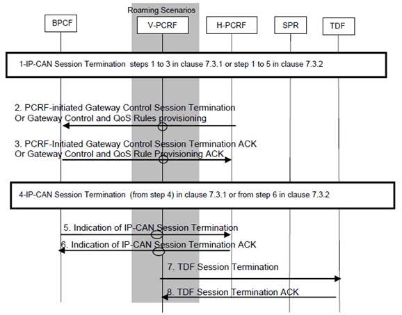
Figure P.7.3.2: IP-CAN Session Termination for either EPC routed or NSWO traffic
(⇒ copy of original 3GPP image)
(⇒ copy of original 3GPP image)
This procedure is applicable for both WLAN and H(e)NB scenario.
For WLAN scenarios, this procedure is performed when the PCRF knows that the 3GPP UE released a PDN connection and request the BPCF to remove the PCC/QoS Rules associated to the terminated IP-CAN session or when the last PDN connection for that 3GPP UE is released to terminate the Gateway Control Session over S9a.
For H(e)NB scenarios, this procedure is performed when the PCRF knows that the last 3GPP UE connecting to the H(e)NB released its last PDN connection and request the BPCF to release the Gateway Control session over S9a or when a PDN connection is released to request the BPCF to remove the QoS Rules associated with the terminated IP-CAN session.
This procedure is the same as described in clauses 7.3.1 and 7.3.2, with the new steps described below:
Step 1.
Steps 5, 6, 7 and 8 are triggered when the BBF access is aware that the UE is detached from BBF access. These steps are not necessarily performed at termination of the IP-CAN session but may occur at a later time.
The PCEF initiates the IP-CAN session termination over Gx, as defined in the clauses 7.3.1 and 7.3.2.
Step 2.
This step is triggered by the IP-CAN session termination indication in step 3 in clauses 7.3.1 and 7.3.2, the PCRF (non-roaming case) or the H-PCRF (roaming case) initiates Gateway Control Session Termination over S9a with the BPCF if this is the last IP-CAN session corresponding to this Gateway Control Session over S9a, or initiates Gateway Control and QoS Rule Provisioning over S9a to remove QoS Rules for the purpose to release resources in the Fixed Broadband Access.
For case 2a, the description of the Gateway Control Session Termination procedure over Gxb* when triggered by the PCRF is described in clause P.7.5.4.
Step 3.
The BPCF reply message contains the result code.
Step 4.
Remaining steps of IP-CAN session termination as described in clause 7.3 from step 4 onwards, with the additions that in .case 2a and roaming scenario, triggered by step2, the vPCRF initiates the Gateway control session termination with the ePDG over Gxb* if the Gateway control session over S9a bound to that IMSI has been terminated.
Step 5.
If the BBF access network is aware of the UE is detached from the BBF access network, the BPCF Initiates IP-CAN session termination to the PCRF (non-roaming) and the V-PCRF (for roaming cases). Triggered by the IP-CAN session termination over S9a, the V-PCRF triggers the IP-CAN session termination over S9.
Step 6.
The PCRF reply message contains the result code for the IP-CAN session terminated.
Step 7.
Triggered by step 6, the PCRF (for non-roaming case) and the V-PCRF (for roaming cases) terminates the TDF session, if exists for the UE local IP address as described in the clause 7.3.
Step 8.
The TDF replies as described in the clause 7.3.
P.7.4 IP-CAN Session Modification p. 228
Both the PCRF-initiated IP-CAN Session Modification Procedure and the PCEF-initiated IP-CAN Session Modification Procedures as described in clause 7.4 are applicable for a 3GPP UE that attaches via a Fixed Broadband Access.
P.7.4.1 PCEF-Initiated IP-CAN Session Modification p. 229
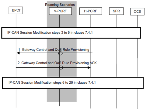
This procedure is applicable for WLAN and H(e)NB scenario. This procedure is performed when the UE Local IP address, H(e)NB Local IP address or the UDP port number is changed and/or when a request for PCC Rules is received from the PCEF. This procedure is the same as described in clause 7.4.1 with the additions described below:
Step 3 in case 1, the PCEF provides the updated UE local IP address, the updated H(e)NB IP address and/or UDP port number to the PCRF.
Step 1.
The PCRF (non-roaming case) initiates Gateway Control and QoS Rule Provisioning with the BPCF to provide either:
Step 2.
- QoS-Rule with the QoS control information (i.e. QCI, GBR, MBR, ARP) and SDF information; and/or
- UE local IP address and/or the UDP port number, the H(e)NB Local IP address may be provided in the request;
- Information (e.g. Session ID) that allows the BPCF to associate the request with the existing Gateway Control Session on S9a so that the fixed access can identify the traffic plane resources that are affected.
The BPCF translates the QoS rule as received of the S9a interface (i.e. SDF information, QCI, GBR, MBR and ARP) into access specific QoS parameters applicable in the BBF domain (the details of the mapping from 3GPP QoS parameters on S9a to QoS parameters applicable in the BBF domain is out of 3GPP scope). The BPCF may respond with a "counter-offer" in form of acceptable bandwidth and/or QoS for one or more SDFs if it cannot provide the requested QoS from the PCRF. The BPCF provides the acceptable QoS in the BBF access using 3GPP QoS parameters (i.e. QCI, GBR, MBR and ARP) and SDF information on S9a interface in the reply if the QoS validation for admission control fails. The PCRF may make a new policy decision, e.g. decide to modify or remove the affected QoS rules.
P.7.4.2 PCRF-Initiated IP-CAN Session Modification p. 229
This procedure is initiated by the PCRF (non-roaming) or by the V-PCRF (roaming). The (V-)PCRF requests the BPCF to perform admission control. Steps (A) show how to provision QoS Rules for the UE IP address(es) allocated by EPC and received over Gx and Steps (B) show how to provision PCC Rules to request admission control for the IP-CAN session for the UE local IP address received over S9a. Note that the TDF that is selected for EPC routed and NSWO traffic may or may not be the same TDF.
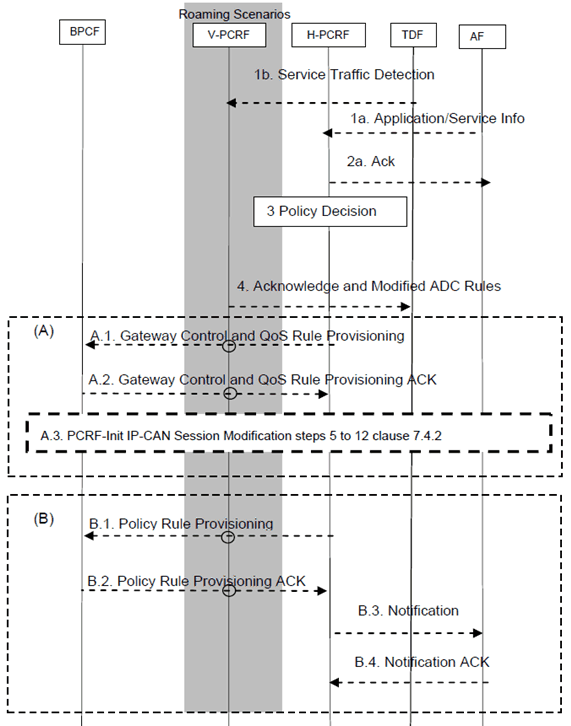
This procedure is applicable for WLAN and H(e)NB scenario. This procedure is the same as described in clause 7.4.2 with the additions described below:
Step 1a, 2a. 1b.
The AF or the TDF provides/revokes service information to the PCRF and detected event triggers if applicable as described in steps 1a, 2a and 1b in clause 7.4.2. For roaming case and for NS-WLAN offloaded traffic, the TDF provides service information and event triggers detected to the V-PCRF.
Step 3.
The PCRF for non-roaming cases or the H-PCRF for roaming cases, makes the authorization and policy decision.
Step 4.
The PCRF acknowledges to the TDF as described in clause 7.4.2.
Step A.
The steps in (A) show PCC signalling to provision QoS Rules for EPC routed traffic.
Step A.1.
Step B.
Triggered by the step 1, the PCRF (non-roaming case) or the v-PCRF (roaming case) initiates Gateway Control and QoS Rule Provisioning to provide:
Step A.2.
- QoS-Rule with the QoS control information (QCI, GBR, MBR, ARP) and SDF information.
- Information (e.g. Session ID) that allows the BPCF to associate the request with the existing Gateway Control Session on S9a so that the fixed access can identify the traffic plane resources that are affected.
The BPCF translates the QoS rule as received of the S9a interface (i.e. QCI, MBR, GBR and ARP) into access specific QoS parameters applicable in the BBF domain (the details of the mapping from 3GPP QoS parameters on S9a to QoS parameters applicable in the BBF domain is out of 3GPP scope). The BPCF may respond with a "counter-offer" in form of acceptable bandwidth and/or QoS for one or more SDFs if it cannot provide the requested QoS from the PCRF. The BPCF provides the acceptable QoS in the BBF access using 3GPP QoS parameters on S9a interface (i.e. QCI, GBR) in the reply if the QoS validation for admission control fails. The PCRF may make a new policy decision, e.g. decide to modify or remove the affected QoS rules.
Step A.3.
PCC Rules are installed in the PCEF as described in clause 7.4.2 and AF is notified if subscribed to the notification of the resource allocation request/modification.
The steps in (B) show PCC signalling to provision PCC Rules for NS-WLAN offloaded traffic.
Step B.1.
Step B.4.
Triggered by the step 3, the PCRF (non-roaming case) or the H-PCRF (roaming case) initiates Policy Rule Provisioning towards the BPCF to provide QoS-Rules for the UE local IP address.
Step B.2.
The BPCF translates the PCC rules as received of the S9a interface (i.e. SDF information, QCI, MBR, GBR and ARP) into access specific QoS parameters applicable in the BBF domain as described in A.2.
Step B.3.
If the AF requested it, the PCRF notifies the AF (e.g. transmission resources are established/released/lost).
The AF acknowledges the notification from the PCRF.
P.7.4.3 BPCF-Initiated IP-CAN Session Modification p. 231
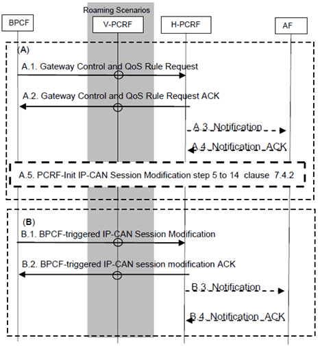
The trigger for this procedure is that the BPCF has pre-empted some resources and wants to report a QoS rule failure to the PCRF, or when the BBF network cannot sustain the Bandwidth allocated to a particular traffic class/DSCP aggregate.
This procedure is applicable for both WLAN and H(e)NB scenarios.
Step A.
The steps in (A) show PCC signalling to report QoS Rule failure to PCRF for the EPC routed traffic.
Step A.1.
Step B.
The BPCF initiates Gateway Control and QoS Rule Request to report QoS Rule failure to PCRF. The request includes a report identifying the QoS Rules that failed and a reason.
Step A.2.
The PCRF acknowledge the request and may initiate PCRF-initiated IP-CAN session modification.
Step 5 to 14 is the same as described in clause 7.4.2.
Step A.3.
If the AF requested it, the PCRF notifies the AF (e.g. transmission resources are released).
Step A.4.
The AF acknowledges the notification from the PCRF.
Step A.5.
The PCRF-initiated IP-CAN session modification as described in clause P.7.4.2 may take place.
The steps in (B) show PCC signalling to report PCC Rule failure to PCRF for NSWO traffic.
Step B.1.
The BPCF initiates IP-CAN session modification to report PCC Rule failure to PCRF.
Step B.2.
The PCRF acknowledges the request.
Step B.3.
If the AF requested it, the PCRF notifies the AF (e.g. transmission resources are released).
Step B.4.
The AF acknowledges the notification from the PCRF.