Content for TS 23.203 Word version: 18.0.0
0…
4…
5…
6…
6.1.4…
6.1.7…
6.1.10…
6.1.17…
6.2…
6.2.2…
6.2.3…
6.3
6.4…
6.8…
7…
7.3…
7.4…
7.7…
7.7.3…
7.8…
A…
A.4…
D…
P…
P.4.2.4…
P.7…
P.7.5…
P.8
Q…
S…
S.7…
S.8.8
T…
7.7 Gateway Control Session Procedures
7.7.1 Gateway Control Session Establishment
7.7.2 Gateway Control Session Termination
...
...
7.7 Gateway Control Session Procedures |R8| p. 150
7.7.1 Gateway Control Session Establishment p. 150
7.7.1.0 General p. 150
There are two cases considered for Gateway Control Session Establishment:
- The PCEF establishes the IP-CAN Session during the Gateway Control session establishment. This happens when the UE attaches to the EPC for the first time and when the UE establishes a new PDN Connection.
- There exists an established IP-CAN Session corresponding to the Gateway Control Session being established. This happens when the BBERF changes, i.e. during BBERF relocation and handovers from and to GTP based EPC.
7.7.1.1 Gateway Control Session Establishment during Attach p. 151

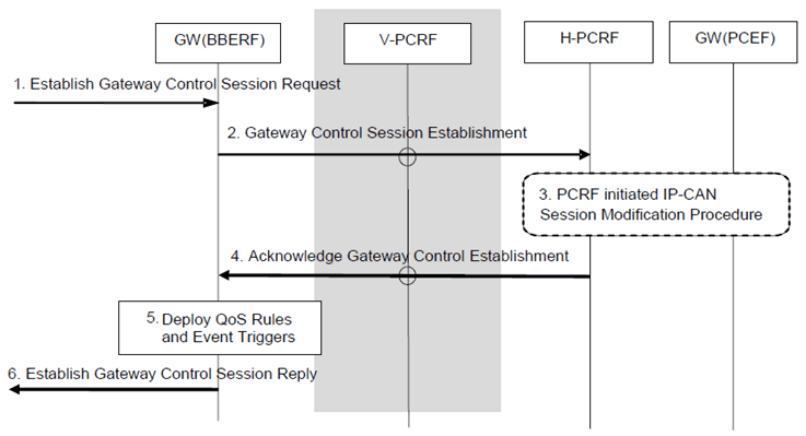
Figure 7.7.1.1-1: Gateway Control Session Establishment during Attach
(⇒ copy of original 3GPP image)
(⇒ copy of original 3GPP image)
This procedure concerns both roaming and non-roaming scenarios. In the roaming case when a Gateway Control Session is used, the V-PCRF should proxy the Gateway Control Session Establishment between the BBERF in the VPLMN and the H-PCRF over S9 based on PDN-Id and roaming agreements.
In the non-roaming case (Figure 5.1-1) the V-PCRF is not involved.
Step 1.
The GW (BBERF) receives an indication that it must establish a Gateway Control Session.
Step 2.
The GW (BBERF) sends the PCRF a Gateway Control Session Establishment. The BBERF includes the following information: IP-CAN Type, UE Identity, PDN Identifier (if known), IP address(es) (if known), an indication that leg linking shall be deferred (applicable for case 2b, as defined in clause 7.1), if available, the PDN Connection Identifier and if available, the IP-CAN bearer establishment modes supported and the indication of BBERF support for the extended TFT filter format. The IP-CAN Type identifies the type of access used by the UE. The UE's identity and PDN Identifier requested are used to identify the subscriber and in PCRF selection to locate the PCRF function with the corresponding IP-CAN session established by the PDN GW. The BBERF may also include the Default Bearer QoS and APN-AMBR (applicable for case 2b, as defined in clause 7.1). An indication that leg linking shall be deferred is included to inform the PCRF that linking the Gateway Control Session to a Gx session shall occur when a matching Gx message is received as described clause 6.2.1.0. Further information is supplied on an access specific basis, as described in the IP-CAN specific Annexes.
Step 3.
For GERAN/UTRAN accesses, if the PCRF is required to interact with the GW (PCEF), the PCRF waits until it gets informed about the establishment of the corresponding IP-CAN session (step 7 of the IP-CAN session establishment procedure) and performs a PCRF initiated IP-CAN session modification procedure with the GW (PCEF).
Step 4.
The PCRF sends an Acknowledge Gateway Control Session Establishment to the GW (BBERF). The PCRF may include the following information: the chosen IP-CAN bearer establishment mode, QoS Rules and Event Triggers. In case 2a a charging ID may be provided together with QoS rules. The QoS policy rules are employed by the GW (BBERF) to perform Bearer Binding. The Event Triggers indicate events that require the GW (BBERF) to report to the PCRF.
Step 5.
The QoS Rules and Event Triggers received by the GW (BBERF) are deployed. This will result in bearer binding being performed, according to the rules. This step may trigger IP-CAN bearer establishment procedures. The details of bearer establishment are IP-CAN specific.
Step 6.
An indication of Gateway Control Session Established is sent to the entity that triggered the initiation of the session.
7.7.1.2 Gateway Control Session Establishment during BBERF Relocation p. 152

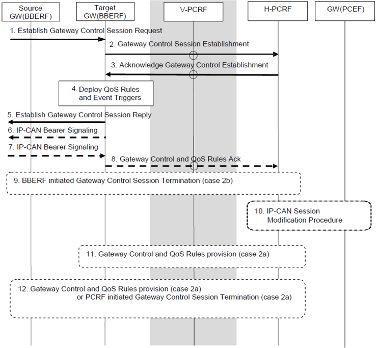
Figure 7.7.1.2-1: Gateway Control Session Establishment during BBERF Relocation
(⇒ copy of original 3GPP image)
(⇒ copy of original 3GPP image)
This procedure concerns both roaming and non-roaming scenarios. In the roaming case when a Gateway Control Session is used, the V-PCRF should proxy the Gateway Control Session Establishment between the BBERF in the VPLMN and the H-PCRF over S9 based on PDN-Id and roaming agreements.
In the non-roaming case (Figure 5.1-1) the V-PCRF is not involved.
Step 1.
The target GW (BBERF) receives an indication that it must establish a Gateway Control Session.
Step 2.
The target GW (BBERF) sends the PCRF a Gateway Control Session Establishment. The BBERF includes the following information: IP-CAN Type, UE Identity, PDN Identifier (if known), IP address(es) (if known), PDN Connection Identifier if available and, if available, the IP-CAN bearer establishment modes supported. The IP-CAN Type identifies the type of access used by the UE. The UE's identity and PDN Identifier requested are used to identify the subscriber and in PCRF selection to locate the PCRF function with the corresponding IP-CAN session established by the PDN GW. The BBERF may also include the Default Bearer QoS and APN-AMBR (applicable for case 2b, as defined in clause 7.1). If the handover state is unknown to the GW (BBERF), as described in TS 23.402, the GW (BBERF) includes an indication to inform the PCRF that linking the Gateway Control Session to a Gx session shall be deferred as described clause 6.2.1.0 (applicable for case 2b, as defined in clause 7.1). Further information is supplied on an access specific basis, as described in the IP-CAN specific Annexes.
Step 3.
If case 2b of clause 7.1 applies and the PCRF correlates the Gateway Control Session with an existing IP-CAN session, it sends an Acknowledge Gateway Control Session Establishment to the target GW (BBERF). The PCRF may include the following information: QoS Rules and Event Triggers. The QoS policy rules are employed by the GW (BBERF) to perform Bearer Binding. The Event Triggers indicate events that require the GW (BBERF) to report to the PCRF. If the BBERF supports NW/UE bearer establishment mode, the PCRF provides to the new BBERF QoS rules corresponding to existing SDFs. For a change of IP-CAN type, the QoS parameters of some of the QoS rules may be changed or some QoS rules may not be provided to the new BBERF, e.g. depending of the capability of the target RAT.
If case 2a of clause 7.1 applies, the PCRF sends an Acknowledge Gateway Control Session Establishment to the target GW (BBERF). The PCRF includes packet filters and QoS information for the CoA in order to establish the initial bearer, e.g. for the DSMIPv6 signalling. The PCRF may also include Event Triggers.
Step 4.
The QoS Rules and Event Triggers received by the target GW (BBERF) are deployed. This will result in bearer binding being performed, according to the rules. This step may trigger IP-CAN bearer establishment procedures. The details of bearer establishment are IP-CAN specific.
Step 5.
An indication of Gateway Control Session Established is sent to the entity that triggered the initiation of the session.
Step 6.
The target GW (BBERF) initiates the IP-CAN Bearer signalling if required for the QoS Rules and Event Triggers deployed in step 4.
Step 7.
The target GW (BBERF) receives the response for the IP-CAN Bearer signalling.
Step 8.
The target GW (BBERF) sends the result of the QoS rule activation to the PCRF, indicating whether the resources requested have been successfully allocated.
Step 9.
If case 2b applies the source GW (BBERF) initiates the Gateway Control Session Termination procedure as defined in clause 7.7.2.1, if appropriate.
Step 10.
If the PCC rules previously provided to the GW (PCEF) need to be removed due to the result of the QoS rule activation as received in step 8, the PCRF updates the GW (PCEF). The PCRF first waits for the PCEF initiated IP-CAN session modification procedure to provide the updates. If the IP-CAN session modification procedure already occurred, the PCRF performs an IP-CAN session modification procedure with the GW (PCEF).
Step 11.
If case 2a applies the PCRF initiates a Gateway Control and QoS Rules Provision procedure towards the target GW (BBERF) as defined in clause 7.7.4, if appropriate, in order to provide any QoS Rules based on the IP-CAN session modification of step 10. In case 2a a charging ID may be provided together with QoS rules.
Step 12.
If case 2a applies the PCRF initiates a Gateway Control and QoS Rules Provision procedure towards the source GW (BBERF) as defined in clause 7.7.4, if appropriate, in order to remove any QoS Rules affected by the GW (BBERF) re-location. If there is no other IP-CAN session established at the source GW (BBERF), the PCRF instead initiates the Gateway Control Session Termination procedure as defined in clause 7.7.2.2.
7.7.2 Gateway Control Session Termination p. 154
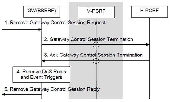
7.7.2.1 GW (BBERF)-Initiated Gateway Control Session Termination p. 154

Step 1.
The GW (BBERF) is requested to terminate its Gateway Control Session.
Step 2.
The GW (BBERF) initiates a Gateway Control Session Termination towards the H-PCRF. If the GW (BBERF) is deployed in a visited network, this procedure is initiated by the GW (BBERF) to the V-PCRF. The V-PCRF forwards the information to the H-PCRF.
Step 3.
The H-PCRF replies to the GW (BBERF) with an Ack Gateway Control Session Termination. If the GW (BBERF) is deployed in a visited network, this information is sent by the H-PCRF to the V-PCRF. The V-PCRF forwards the information to the GW (BBERF).
Step 4.
The GW (BBERF) removes the QoS rules and Event triggers associated with the Gateway Control Session. This means the GW (BBERF) ceases its bearer binding and other Gateway Control functions associated with the QoS rules and Event Triggers.
Step 5.
The GW (BBERF) has completed terminating the session and can continue with the activity that prompted this procedure.
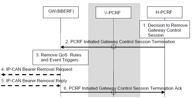
7.7.2.2 PCRF-Initiated Gateway Control Session Termination p. 155

This procedure concerns both roaming and non-roaming scenarios. In the roaming case when a Gateway Control Session is used, the V-PCRF should proxy the Gateway Control Session Termination between the BBERF in the VPLMN and the H-PCRF over S9 based on PDN-Id and roaming agreements.
In the non-roaming case (Figure 5.1-1) the V-PCRF is not involved.
Step 1.
The PCRF is requested to terminate its Gateway Control Session.
Step 2.
The PCRF sends a PCRF-Initiated Gateway Control Session Termination to the GW (BBERF).
Step 3.
The GW (BBERF) removes the QoS rules and Event triggers associated with the Gateway Control Session. This means the GW (BBERF) ceases its bearer binding and other Gateway Control functions associated with the QoS rules and Event Triggers.
Step 4.
If the bearer(s) corresponding to the removed QoS rules are still established, the GW (BBERF) initiates an IP-CAN specific bearer removal procedure.
Step 5.
The GW (BBERF) receives the response for the IP-CAN specific bearer removal procedure.
Step 6.
The GW (BBERF) replies to the PCRF with an PCRF-Initiated Gateway Control Session Termination acknowledgement.