Content for TR 26.998 Word version: 18.0.0
0…
4…
4.2…
4.2.2…
4.2.2.2
4.2.2.3
4.2.2.4
4.2.3…
4.3…
4.4…
4.5…
4.6…
4.6.4…
4.6.5…
4.6.8…
5
6…
6.2…
6.2.4…
6.2.4.2
6.2.5…
6.3…
6.3.4…
6.3.4.2
6.3.5…
6.4…
6.4.4
6.4.5…
6.5…
6.5.4
6.5.5
6.5.6…
6.6…
6.6.4
6.6.5…
7…
8…
8.9
9
A…
A.2
A.3…
A.4
A.5
A.6
A.7…
A.3 Use Case 18: Streaming of volumetric video for glass-type MR devices
A.3.1 Use case description
A.3.2 Call flow for STAR UE
A.3.3 Call flow for EDGAR UE
...
...
A.3 Use Case 18: Streaming of volumetric video for glass-type MR devices p. 106
A.3.1 Use case description p. 106
| Use Case Description: Streaming volumetric video for glass-type MR devices |
|---|
| Bob and Patrick are gym instructors and run a gym 'VolFit'. 'VolFit' provides their clients with a mixed-reality application to choose and select different workout routines on a 5G-enabled OHMD. The workout routines are available as high-quality photorealistic volumetric videos of the different gym instructors performing the routines. Bob and Patrick book a professional capture studio for a high-quality photorealistic volumetric capture of the different workout routines for their clients. Bob and Patrick perform the workout routines in the studio capture area. The studio captures Bob and Patrick volumetrically. Alice is a member of 'VolFit' gym. Alice owns a 5G-enabled glass-type OHMD device. The 'VolFit' MR application is installed on her OHMD. The OHMD has an untethered connection to a 5G network. Alice wears her OHMD device. The MR application collects and maps spatial information of Alice's surrounding from the set of sensors available on the OHMD. The OHMD can further process the spatial mapping information to provide a semantic description of the Alice's surrounding. Alice wants to learn a workout routine from her instructors, Bob and Patrick. The photorealistic volumetric videos of Alice's instructors are streamed to the MR application installed on her OHMD. The MR application allows Alice to position the volumetric representations of Bob and Patrick on real-world surfaces in her surroundings. Alice can move around with 6DoF, and view the volumetric videos from different angles. The volumetric representations are occluded by real-world objects in the XR view of Alice; when Alice move to a location where the volumetric objects are positioned behind real-world objects or vice-versa. During the workout session, Alice gets the illusion that Bob and Patrick are physically present in her surroundings, to teach her the workout routine effectively. The MR application allows Alice to play, pause and rewind the volumetric videos. The functions can be triggered for example by hand-gestures, a dedicated controller connected to the OHMD, etc. |
| Categorization |
|
Type:
MR (XR5G-A1, XR5G-A2, XR5G-A4, XR5G-A5)
Degrees of Freedom:
6DoF
Delivery:
Streaming, Split-rendering
Device:
OHMD with/without a controller
|
| Preconditions |
|
| Requirements and QoS/QoE Considerations |
|
| Feasibility |
Volumetric content production:
|
| Potential Standardization Status and Needs |
The following aspects may require standardization work:
|
A.3.2 Call flow for STAR UE p. 109
The call flow of the establishment of the AR session for STAR UE is shown in Figure A.3.2-1:
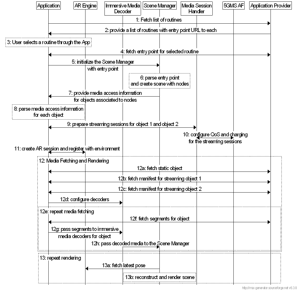
A description of the steps is provided:
Step 1.
The following media is assumed for this use case:
User starts the app. The app connects to the cloud to fetch a list of exercise routines for the user
Step 2.
The AP sends a list of routines to the app. Each routine is associated with an entry point for that routine. The entry point is typically a scene description that describes the objects in the scene and anchors the scene with the world space.
Step 3.
The user selects a routine in the app
Step 4.
The app fetches the scene description for the selected routine from the application provider
Step 5.
The app initializes the Scene Manager and passes the entry point to it.
Step 6.
The Scene Manager parses entry point to extract information about the required objects in the scene. In this case, the coach, the student, and a speaker are the 3 objects that will be rendered in the scene.
Step 7.
The Scene Manager informs the application about the required media that needs to be accessed.
Step 8.
The app parses the information about the media objects and determines how and when to access each of them.
Step 9.
The app informs the MSH that it will start 2 streaming sessions for the 2 dynamic objects.
Step 10.
The MSH shares the information with the AF and based on existing provisioning by the Application Provider, the AF may request QoS and charging modifications to the PDU sessions.
Step 11.
The App creates a new XR session and anchors the scene to a selected space in the XR session.
Step 12.
The media exchange begins:
Step 13.
- The static object in the scene, the loudspeaker, is fetched by the App
- The manifest for object 1 is retrieved
- The manifest for object 2 is retrieved
- The App configures the immersive video decoders based on the components of each object
- Media segment for each component of each object is fetched
- The segment is decoded and passed to the immersive media renderer
The Scene Manager periodically renders a frame by iteratively reconstructing each object and rendering it to a swapchain image. The swapchain image is passed to the AR Runtime for rendering to the HMD device.
- An entry point: a scene description that describes the objects in the scene.
- Dynamic objects for the coach and student: these can be dynamic meshes, animated meshes, or point clouds.
- Static object for the loudspeaker: this can be a static mesh.
- Spatial audio: representing the vocal instructions associated with the dynamic object of the coach.
- Spatial audio: representing the music for which the loudspeaker is the source.
A.3.3 Call flow for EDGAR UE p. 111
The call flow of the establishment of the AR session for EDGAR UE is shown in Figure A.3.3-1:
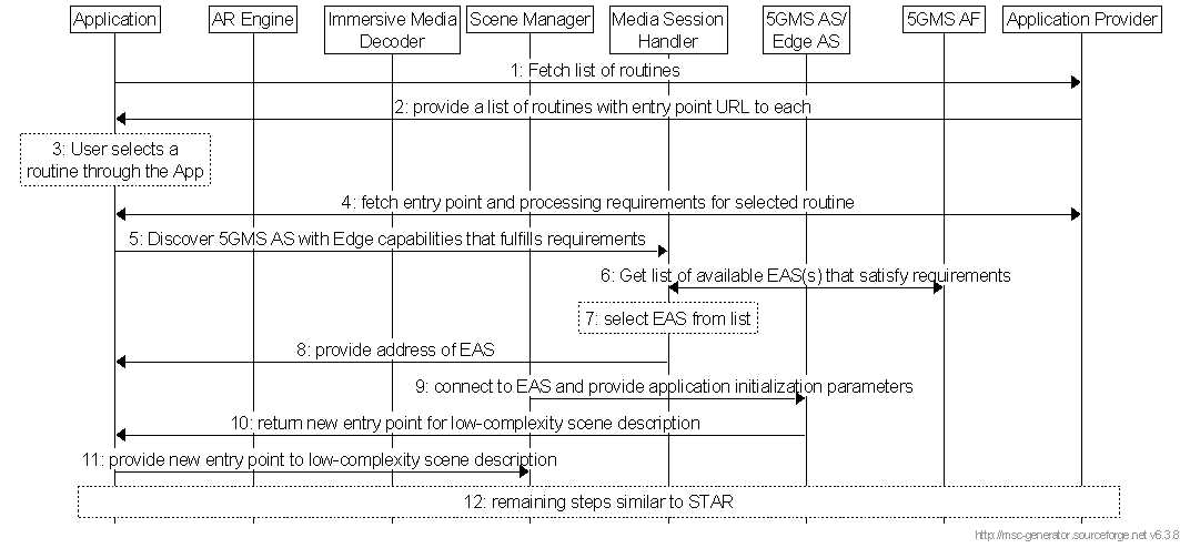
A description of the steps is provided:
Step 1.
User starts the app. The app connects to the cloud to fetch a list of exercise routines for the user
Step 2.
The AP sends a list of routines to the app. Each routine is associated with an entry point for that routine. The entry point is typically a scene description that describes the objects in the scene and anchors the scene with the world space.
Step 3.
The user selects a routine of preference in the app
Step 4.
The application sends a request for the entry point to the selected content. The Application Provider responds with an entry point to a scene description and a list of requirements for optimal processing of the scene.
Step 5.
The application determines that EDGE support is required and sends a request to the MSH to discover an appropriate Edge AS that can serve the application.
Step 6.
The MSH sends the requirements to the AF and receives a list of candidate EAS(s)
Step 7.
The MSH selects an appropriate EAS from the list of candidates.
Step 8.
The MSH provides the location of the EAS to the application.
Step 9.
The application connects to the EAS and provides initialization information. The initialization information contains: the URL to the scene description entry point or the actual scene description, its current processing capabilities, supported formats and protocols, etc.
Step 10.
The EAS configures the server application accordingly and generates a customized entry point for the client. The formats depend on the capabilities of the UE. The EAS adjusts the amount of processing performed by the EAS based on the current capabilities of the application. For example, The EAS may perform scene lighting and ray tracing and then generate a lightweight 3D scene description for the application. A less-capable UE may receive a more flattened scene, that contains stereo eye views and some depth information.
Step 11.
The App initializes the Scene Manager with the new low-complexity entry point.
Step 12.
The rest of the steps are similar to steps 6-10 from the STAR call flow.
![]()
![]()
![]()