Content for TR 26.998 Word version: 18.0.0
0…
4…
4.2…
4.2.2…
4.2.2.2
4.2.2.3
4.2.2.4
4.2.3…
4.3…
4.4…
4.5…
4.6…
4.6.4…
4.6.5…
4.6.8…
5
6…
6.2…
6.2.4…
6.2.4.2
6.2.5…
6.3…
6.3.4…
6.3.4.2
6.3.5…
6.4…
6.4.4
6.4.5…
6.5…
6.5.4
6.5.5
6.5.6…
6.6…
6.6.4
6.6.5…
7…
8…
8.9
9
A…
A.2
A.3…
A.4
A.5
A.6
A.7…
4.6.5 MPEG Scene Description
4.6.6 MPEG-I Video Decoding Interface for Immersive Media
4.6.7 MPEG-I Carriage of Point Cloud Compression Data
...
...
4.6.5 MPEG Scene Description p. 49
A key technology in enabling immersive 3D user experiences is scene description. Scene description is used to describe the composition of a 3D scene, referencing and positioning the different 2D and 3D assets in the scene. The information provided in the scene description is then used by an application to render the 3D scene properly, using techniques such as Physically-Based Rendering (PBR) that produce realistic views.
A scene description is typically organized as a directed acyclic graph, typically a plain tree-structure, that represents an object-based hierarchy of the geometry of a scene and its attributes/properties. Nodes are organized in a parent-child hierarchy known informally as the node hierarchy. A node is called a root node when it doesn't have a parent. Any node may define a local space transformation.
Spatial transformations are represented by transformation matrices or separate transform operations such as translation, rotation, and scaling. The transformations are applied hierarchically and iteratively from the root node down to the child nodes. Scene description also support animation nodes that allow to animate properties of the corresponding objects over time.
This structure of scene description has the advantage of reduced processing complexity, e.g. while traversing the graph for rendering. An example operation that is simplified by the graph representation is the culling operation, where branches of the graph are omitted, if deemed that the parent node's space is not visible or relevant (level of detail culling) to the rendering of the current view frustum.
To address the needs of immersive applications, MPEG is finalizing the development of a scene description solution that adds extensions to glTF to support scene description. glTF 2.0 [22] provides a solid and efficient baseline for exchangeable and interoperable scene descriptions. However, glTF 2.0 has traditionally been focused on static scenes and assets, which makes it unfit to address the requirements and needs of dynamic and rich 3D scenes in immersive environments.
As part of its effort to define solutions for immersive multimedia, MPEG has identified the following gaps in glTF 2.0:
- No support for timed media
- No support for audio
- Limited support for interactions with the scene and the assets in the scene
- No support for local and real-time media, which are crucial for example for AR experiences

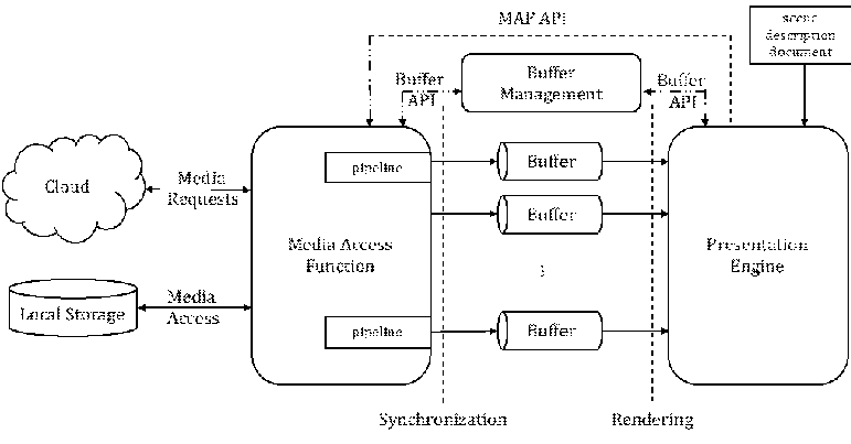
The design focuses mainly on buffers as means for data exchange throughout the media access and rendering pipeline. It also defines a Media Access Function API to request media that is referenced by the scene description, which will be made accessible through buffers.
4.6.6 MPEG-I Video Decoding Interface for Immersive Media p. 50
The aim of VDI (MPEG-I part 13) is to address the challenges for media applications to handle multiple decoder instances running in parallel, especially in the case of immersive media. To this end, the scope of the VDI specification covers the interface between a media application and the Video Decoding Engine (VDE) sitting on the device.
Typically, hardware decoder is exposed via API to the application. Proprietary APIs exist but also standardised one such as Khronos® OpenMaxTM and Khronos® Vulkan® Video extension. However, those APIs only allow the instantiation of video decoder instances independently from each other up to the point where the hardware decoding platform may no longer sustain the application requests, for instance due to lack of memory.
Extensions specified in MPEG-I VDI (ISO/IEC 23090-13) allow the AR/MR application to query the capacity to simultaneously decode multiple operation points (generally specified by profile, tier and levels). This allows a better predictability of what bitstreams may be decoded by the application.
Additionally, VDI also defines bitstream manipulation functions for the video codecs HEVC, VVC and EVC that enable the merging and the splitting of bitstreams. This aspect of elementary stream manipulation is covered by the so-called input formatting function in MPEGI VDI. This way, an application may adapt the number of the decoder needed when several input bitstreams are to be decoded to the extent the merging operations has been enabled by the proper encoding constraints.
4.6.7 MPEG-I Carriage of Point Cloud Compression Data p. 50
For the encapsulation and storage of coded volumetric media, two MPEG systems standards may be considered as potential technologies: ISO/IEC 23090-10 [24] and ISO/IEC 23090-18 [25]. ISO/IEC 23090-10 and ISO/IEC 23090-18 define how to structure and carry the various components in a V3C bitstream or G-PCC bitstream, respectively, in an ISOBMFF media container to support flexible and partial access (e.g., using multiple component tracks and tile tracks) as well as adaptive streaming. Both specifications support single track encapsulation as well as multi-track encapsulation, where different components of the bitstream are carried in separate tracks in the container. In addition, these standards also define metadata tracks that may be associated with the main media tracks and carry additional timed information that signal changes in the spatial partitioning of the volumetric content and the mapping to different independently decodable tiles as well as viewport-related information.
In addition, ISO/IEC 23090-10 and ISO/IEC 23090-18 define how to signal V3C and G-PCC content in a DASH MPD file. This includes defining new DASH descriptors that signal metadata about the type of component carried by each adaptation set and using pre-selections to group the adaptation sets of the different components associated with the volumetric media content. Other descriptors are also defined for signalling independently decoded spatial sub-divisions of the content to support partial streaming. In addition to signalling for DASH-based delivery, ISO/IEC 23090-10 and ISO/IEC 23090-18 also define descriptors for signalling volumetric media assets for delivery over MMT.