Content for TS 26.501 Word version: 18.0.0
1…
4…
4.2…
4.2.2…
4.3…
4.5…
4.6…
4.7…
5…
5.2…
5.3…
5.3.2
5.4…
5.5…
5.5.3…
5.6…
5.7…
5.7.3
5.7.4…
5.8
5.9…
5.10…
5.10.5
5.10.6
5.11…
6…
6.2…
6.3…
6.5…
6.8…
7…
8…
8.2
A…
A.3…
A.5…
A.7…
A.9
A.10
A.11
A.12
A.13
A.14
A.15
B…
B.3
C…
C.3
C.4
C.5
D…
6.5 Providing 5GMSu AF-based Network Assistance
6.6 Providing Remote Control
6.7 RAN Signalling based Support for Uplink Network Assistance
...
...
6.5 Providing 5GMSu AF-based Network Assistance p. 94
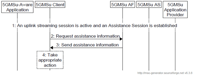
The procedure defines the network assistance from a 5GMSu AF.

Steps:
6.6 Providing Remote Control p. 95
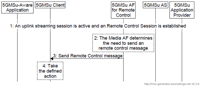
The procedure defines the remote control from a 5GMSu AF. Note that the 5GMSu AF for remote control may be deployed as a network based function or a UE-based function.

Steps:
Step 1.
An uplink streaming session is active. The Remote Control Session is established with the 5GMSu AF.
Step 2.
The 5GMSu AF for Remote Control determines the need to send a remote control message.
Step 3.
The remote control message is sent to the 5GMSu Client.
Step 4.
The 5GMSu Client takes the defined action specified in the remote control message.
6.7 RAN Signalling based Support for Uplink Network Assistance p. 96
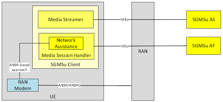
Figure 6.7-1 depicts an uplink streaming architecture where RAN signalling is employed to support uplink Network Assistance functionality.
The RAN in the architecture contains control plane and user plane entities that interact with peer control and user plane entities in the UE, in the request/response for boost of the uplink streaming data rate, and subsequent media transport. The user plane functionality as shown in Figure 6.7-1 (solid line going from UE to RAN to 5GMSu AS) illustrates the scheduling/passthrough functionality associated with user plane communications, governed by the RAN, as result of the uplink assistance messaging over the control plane (shown by dotted line between the UE and RAN). It is assumed in this case that 5GMSu AF-based Network Assistance is not utilized.
It should be noted that although the 5GMSu AF is not utilized when RAN signalling based network assistance is performed, it is assumed that there is a higher level network entity which coordinates and tracks network assistance performed using RAN signalling versus application signalling for individual UEs.
