Content for TS 23.502 Word version: 19.0.0
1…
4.2.2.2.2
4.2.2.2.3…
4.2.2.3…
4.2.3…
4.2.3.3
4.2.4…
4.2.6
4.2.7…
4.2.9…
4.2.11…
4.2.11.5…
4.3…
4.3.2.2.2
4.3.2.2.3…
4.3.3…
4.3.3.3
4.3.4…
4.3.4.3
4.3.5…
4.3.5.2…
4.3.5.4…
4.3.5.6…
4.3.6…
4.4…
4.5…
4.9…
4.9.1.3…
4.9.2…
4.11…
4.11.1…
4.11.1.2.2
4.11.1.2.3
4.11.1.3…
4.11.1.3.3…
4.11.1.4…
4.11.1.5…
4.11.2…
4.11.3…
4.12…
4.12.6…
4.12a…
4.12b…
4.13…
4.13.4…
4.13.6…
4.14…
4.15…
4.15.3.2.5…
4.15.4…
4.15.6…
4.15.6.7…
4.15.6.13…
4.15.6.14…
4.15.9…
4.15.9.4…
4.15.13…
4.15.13.4…
4.16…
4.16.4…
4.16.8…
4.16.11…
4.16.14…
4.16.15…
4.17…
4.17.9…
4.18…
4.19…
4.22…
4.23…
4.23.7…
4.23.7.3.3
4.23.7.3.4…
4.23.9…
4.23.9.4…
4.23.11…
4.24…
4.25…
4.25.6…
4.26…
5…
5.2.3…
5.2.5…
5.2.6…
5.2.7…
5.2.8…
5.2.9…
5.2.12…
5.2.18…
A…
E…
F…
G
H…
4.23.9.4 Simultaneous change of Branching Point or UL CL and additional PSA controlled by I-SMF
4.23.9.5 Simultaneous change of Branching Points or UL CLs controlled by different I-SMFs
4.23.10 CN-initiated selective deactivation of UP connection of an existing PDU Session involving I-SMF
...
...
4.23.9.4 Simultaneous change of Branching Point or UL CL and additional PSA controlled by I-SMF p. 634
This clause describes simultaneous change of UL-CL/BP function and additional PSA, e.g. addition of a new UL CL/BP and PDU Session Anchor (i.e. PSA2) and release of the existing UL CL/BP and additional PDU Session Anchor (i.e. PSA0), with target UPF(s) and source UPF(s) are all controlled by I-SMF.
This procedure may be triggered after N2 handover or Xn based handover procedure.
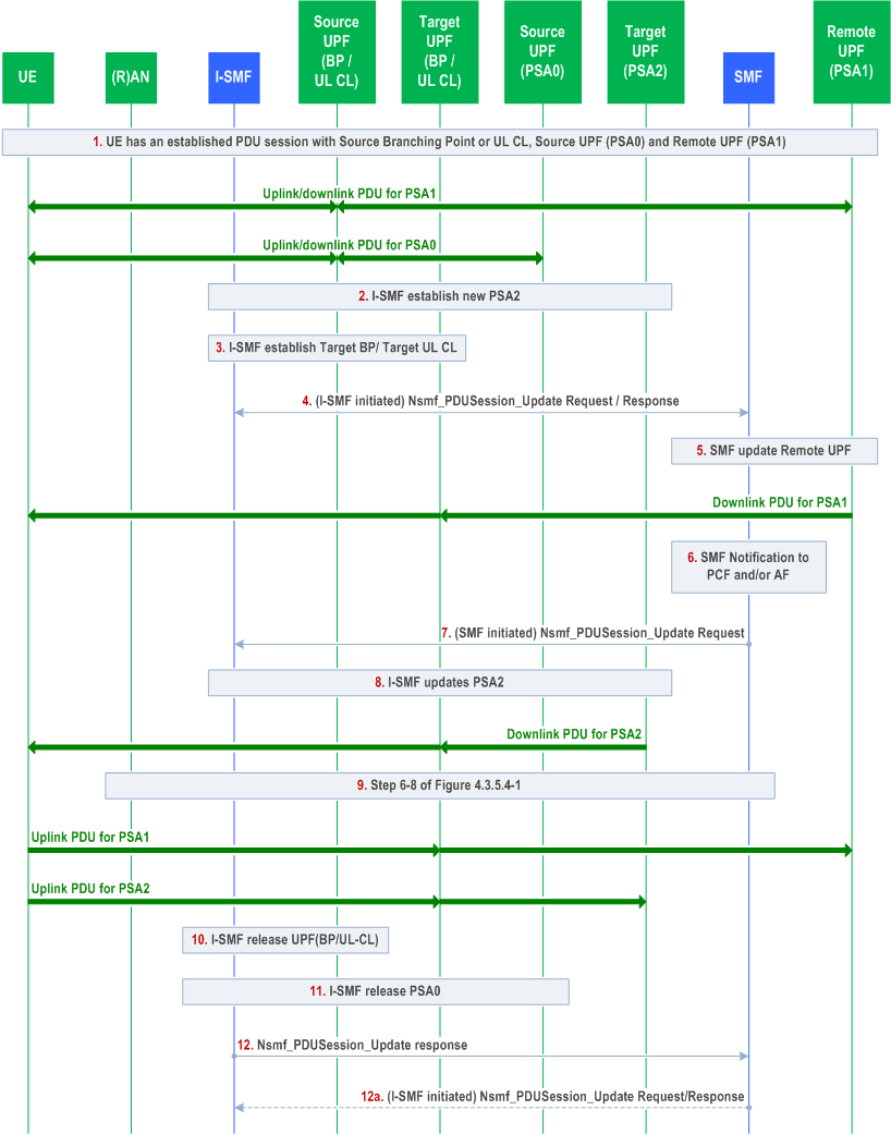
Comparing to the clause 4.23.9.3, this procedure in addition changes the source UL-CL/BP by a target UL-CL/BP.
Step 1-2.
These steps are the same steps 1-2 in clause 4.23.9.3.
Step 3.
The I-SMF selects a UPF and using N4 establishes the target UL CL or BP of the PDU Session.
Step 4.
The I-SMF invokes Nsmf_PDUSession_Update Request (Indication of Change of traffic offload, (new allocated IPv6 prefix @PSA2, DNAI(s) supported by PSA2), (Removal of IPv6 prefix @PSA0, DNAI(s) supported by PSA0), DL Tunnel Info of the new UL CL/Branching Point) to SMF.
The DL Tunnel Info of target UL CL/Branching Point is provided to SMF.
Step 5.
The SMF updates the remote PSA (PSA1) via N4 with the DL Tunnel Info of the Target UL CL/BP for the downlink traffic.
Step 6-8.
These steps are the same as steps 4-6 in clause 4.23.9.3.
If EAS session continuity upon UL CL relocation is required, in step 7 the SMF provides the I-SMF additionally with an indication that a N9 forwarding tunnel to support the EAS session continuity is required, UL traffic filter for N9 forwarding by the target UL CL and the value of the timer to detect the end of activity on the N9 forwarding tunnel to support the EAS session continuity. Based on the received information, the I-SMF uses N4 to establish between the source UL CL and target UL CL the N9 forwarding tunnel to support the EAS session continuity. The I-SMF configures the source UL CL to forward traffic received from source L-PSA related to that PDU session toward the target UL CL via the N9 forwarding tunnel.
Step 9.
Same as steps 6-8 of clause 4.3.5.4. The I-SMF updates (R)AN for uplink traffic.
Step 10-11.
If a N9 forwarding tunnel to support the EAS session continuity is not established between the source UL CL and target UL CL, the I-SMF releases via N4 the source UL-CL/BP as the source UL-CL/BP is replaced by the target UL-CL/BP. The I-SMF also releases via N4 the PSA0 if PSA0 is not collocated with source UL CL/BP;
Step 12.
This step is the same as step 9 in clause 4.23.9.3.
Step 12a.
If a N9 forwarding tunnel to support the EAS session continuity is established between the source UL CL and target UL CL, the I-SMF releases the source UL-CL/BP and PSA0 and the N9 forwarding tunnel in target UL CL when detection of no active traffic over the N9 forwarding tunnel takes place per the value of the timer to detect the end of activity on the N9 forwarding tunnel to support the EAS session continuity received from SMF. The detection can be done by Source UL CL, which notifies the I-SMF of no active traffic over the N9 forwarding tunnel.
The I-SMF invokes Nsmf_PDUSession_Update Request to inform the SMF of the release of the resource in UL CL/BP and PSA0 for the PDU Session.
4.23.9.5 Simultaneous change of Branching Points or UL CLs controlled by different I-SMFs |R17| p. 636
This clause describes simultaneous change of UL-CL/BP function and additional PSA, e.g. addition of a new UL CL/BP and PDU Session Anchor (i.e. PSA2) and release of the existing UL CL/BP and PDU Session Anchor (i.e. PSA0), with target UPF(s) and source UPF(s) are all controlled by different I-SMF(s).
This procedure may be triggered after N2 handover or Xn based handover procedure.
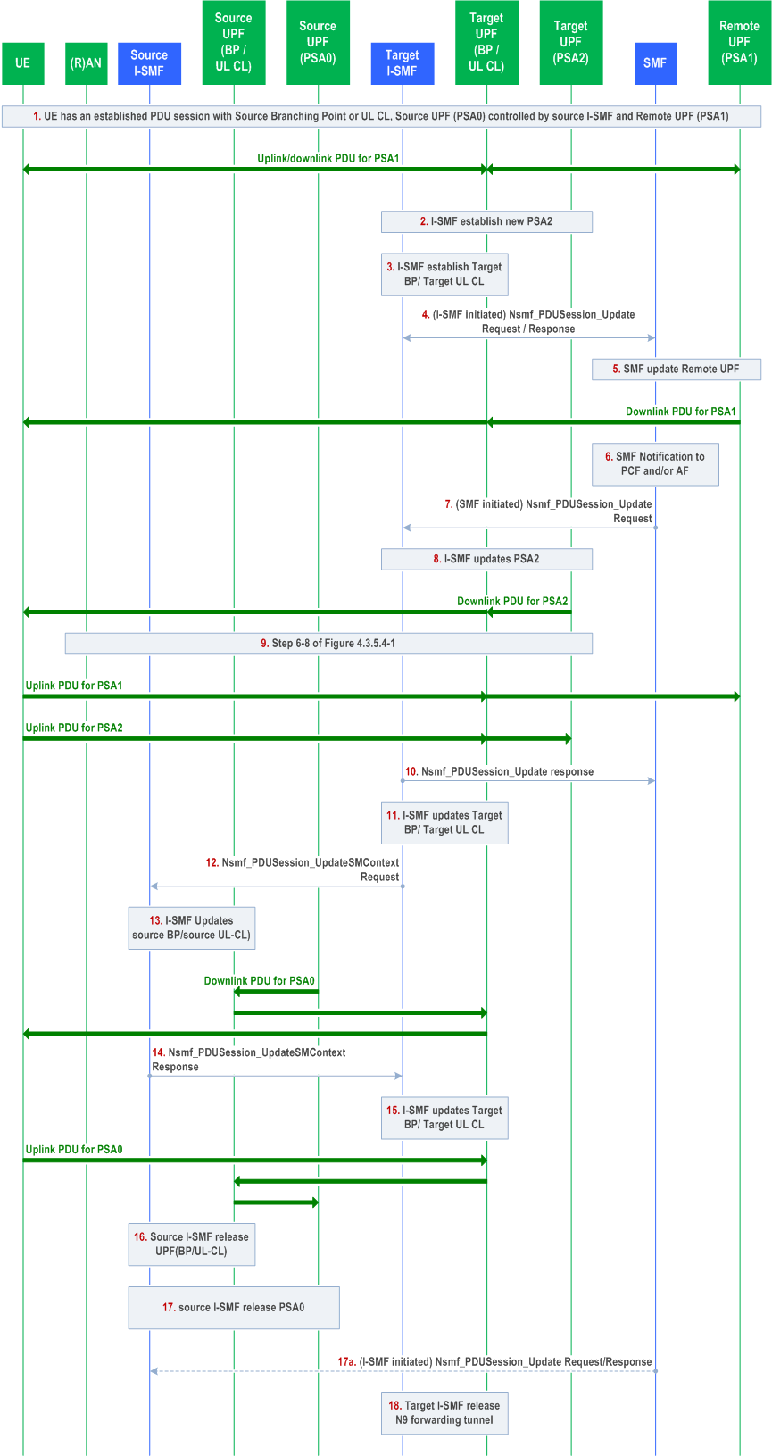
Step 1.
UE has established PDU Session with Source Branching Point or UL CL and Source UPF (PSA0) controlled by source I-SMF and Remote PSA. The UE has mobility with I-SMF change, e.g. handed over from a source RAN to a target RAN. After mobility, the path between Target I-UPF and Remote PSA (PSA1) has been established.
Step 2.
This step is the same as steps 2 in clause 4.23.9.3.
Step 3.
Same as in step 3 of Figure 4.23.9.4-1.
Step 4.
Same as in step 4 of Figure 4.23.9.4-1.
Step 5.
Same as in step 5 of Figure 4.23.9.4-1..
Step 6-8.
These steps are the same as steps 4-6 in clause 4.23.9.3 with the following enhancement:
In step 7, to support EAS session continuity upon UL CL relocation the SMF provides the target I-SMF with an indication that a N9 forwarding tunnel to support the EAS session continuity is required, UL traffic filter for N9 forwarding by the target UL CL and the value of the timer to detect the end of activity on the N9 forwarding tunnel to support the EAS session continuity. Based on the received information, the target I-SMF installs corresponding N4 rules in the target UL CL for forwarding of uplink traffics via the N9 forwarding tunnel. The time interval for User Plane inactivity report is also provisioned to UL CL per the timer value received from SMF.
Step 9.
Same as in step 9 of Figure 4.23.9.4-1.
Step 10.
This step is the same as step 9 in clause 4.23.9.3.
The SMF triggers the procedure from step 11 onwards to support EAS session continuity upon UL CL relocation.
Step 11.
If N9 forwarding tunnel to support the EAS session continuity is required based on indication received from SMF in step 7, the target I-SMF request target UL CL to allocate N9 forwarding tunnel info via N4 session modification procedure.
Step 12.
The target I-SMF invokes Nsmf_PDUSession_UpdateSMContext Request (N9 forwarding tunnel required, target UL CL N9 forwarding tunnel info, value of the timer to detect the end of activity on the N9 forwarding tunnel to support the EAS session continuity) toward the source I-SMF.
Step 13.
The source I-SMF triggers N4 modification procedure to request the source UL CL to establish the N9 forwarding tunnel to support the EAS session continuity. The source I-SMF provides the target UL CL N9 forwarding tunnel info to the source UL CL and receives the source UL CL N9 forwarding tunnel info from the source UL CL. The source I-SMF configures the source UL CL to forward traffic received from source L-PSA related to that PDU session toward the target UL CL via the N9 forwarding tunnel.
The source I-SMF configures a time interval for the source ULCL for the detection of no active traffic over the N9 forwarding tunnel, which is based on the value of the timer to detect the end of activity on the N9 forwarding tunnel to support the EAS session continuity as received from target I-SMF.
After this step, the downlink data can be forwarded via N9 forwarding tunnel from the source L-PSA (PSA0).
Step 14.
The source I-SMF sends Nsmf_PDUSession_UpdateSMContext Response (source UL CL N9 forwarding to support the EAS session continuity tunnel info).
Step 15.
Based on the traffic filter information received from SMF at step 7 and source UL CL N9 forwarding tunnel to support the EAS session continuity info, the target I-SMF request the target UL CL to forward related UL traffic via N9 forwarding tunnel to support the EAS session continuity.
The target I-SMF configures a time interval for the target ULCL for the detection of no active traffic over the N9 forwarding tunnel, which is based on the value of the timer to detect the end of activity on the N9 forwarding tunnel to support the EAS session continuity received from SMF.
After this step, the uplink data can be forwarded via N9 forwarding tunnel toward the source L-PSA (PSA0).
Step 16-17.
Upon detection of no active traffic over the N9 forwarding tunnel to support the EAS session continuity, the source I-SMF releases via N4 the source UL-CL/BP The Source I-SMF also releases via N4 the PSA0 if PSA0 is not collocated with source UL CL/BP.
Step 17a.
The source I-SMF invokes Nsmf_PDUSession_Update Request to inform the SMF of the release of the resource in the UL CL/BP and the PSA0 for this PDU Session.
Step 18.
Upon detection of no active traffic over the N9 forwarding tunnel to support the EAS session continuity, the Target I-SMF releases the N9 forwarding tunnel in Target UL CL and remove the related filter.
4.23.9a Void
4.23.10 CN-initiated selective deactivation of UP connection of an existing PDU Session involving I-SMF p. 639
For the CN-initiated selective deactivation of UP connection of an existing PDU Session procedure, if the PDU Session involved I-SMF, the procedure defined in clause 4.3.7 are impacted as following:
- The SMF and UPF in the procedure are replaced by the I-SMF and I-UPF.
![]()
![]()
![]()