Content for TS 23.216 Word version: 18.0.0
6.2.2.2 SRVCC from E-UTRAN to UTRAN with PS HO or GERAN with DTM HO support
6.2.2.3 vSRVCC from E-UTRAN to UTRAN with PS HO support
6.2.2.4 vSRVCC from E-UTRAN to UTRAN without PS HO support
6.2.3 Returning back to E-UTRAN
...
...
6.2.2.2 SRVCC from E-UTRAN to UTRAN with PS HO or GERAN with DTM HO support p. 44
Depicted in Figure 6.2.2.2-1 is a call flow for SRVCC from E-UTRAN to UTRAN or GERAN with DTM HO support, including the handling of the non-voice component. The flow requires that eNB can determine that either the target is UTRAN with PS HO or the target is GERAN with DTM support and the UE is supporting DTM.
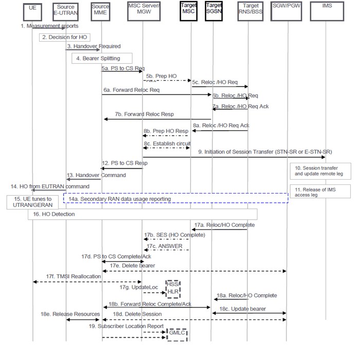
Figure 6.2.2.2-1: SRVCC from E-UTRAN to UTRAN with PS HO or GERAN with DTM HO support
(⇒ copy of original 3GPP image)
(⇒ copy of original 3GPP image)
Step 1.
If the MME determines that only the relocation of the voice bearer but not the relocation of one or more PS bearers succeeds, then the MME proceeds with step 13 after receiving SRVCC PS to CS Response from the MSC Server in step 12 and both UE and MME continue the procedure as described in clause 6.2.2.1A.
UE sends measurement reports to E-UTRAN.
Step 2.
Based on UE measurement reports the source E-UTRAN decides to trigger an SRVCC handover to UTRAN/GERAN.
Step 3.
If target is UTRAN, the source E-UTRAN sends a Handover Required (Target ID, generic Source to Target Transparent Container, SRVCC HO indication) message to the source MME. SRVCC HO indication indicates to MME that this is for CS+PS HO.
If target is GERAN, the source E-UTRAN sends a Handover Required (Target ID, generic Source to Target Transparent Container, additional Source to Target Transparent Container, SRVCC HO Indication) message to the source MME. The E-UTRAN places the "old BSS to new BSS information IE" for the CS domain in the additional Source to Target Transparent Container. The differentiation between CS and PS containers is described in TS 36.413. In this case, the MME identifies from SRVCC HO Indication that this is a request for a CS+PS handover.
Step 4.
Based on the QCI associated with the voice bearer (QCI 1) and the SRVCC HO Indication, the source MME splits the voice bearer from all other PS bearers and initiates their relocation towards MSC Server and SGSN, respectively.
Step 5a.
Source MME initiates the PS-CS handover procedure for the voice bearer by sending a SRVCC PS to CS Request (IMSI, Target ID, STN-SR, C-MSISDN, Source to Target Transparent Container, MM Context, Emergency Indication) message to the MSC Server. If SRVCC with priority is supported, the MME also includes priority indication in SRVCC PS to CS Request if it detects the SRVCC requires priority handling. The detection is based on the ARP associated with the EPS bearer used for IMS signalling. The priority indication corresponds to the ARP information element. The Emergency Indication and the equipment identifier are included if the ongoing session is emergency session. Authenticated IMSI and C-MSISDN shall also be included if available. The message includes information relevant to the CS domain only. MME received STN-SR and C-MSISDN from the HSS as part of the subscription profile downloaded during the E-UTRAN attach procedure. MM Context contains security related information. CS security key is derived by the MME from the E-UTRAN/EPS domain key as defined in TS 33.401. The CS Security key is sent in the MM Context.
Step 5b.
MSC Server interworks the PS-CS handover request with a CS inter-MSC handover request by sending a Prepare Handover Request message to the target MSC. If SRVCC with priority is supported and the MSC Server receives the priority indication (i.e. ARP) in the SRVCC PS to CS Request, the MSC server/MGW sends Prepare Handover Request message to the Target MSC with priority indication mapped from the ARP. The MSC Server maps the ARP to the priority level, pre-emption capability/vulnerability for CS services based on local regulation or operator settings. The priority indication indicates the CS call priority during handover as specified in TS 25.413 for UMTS and TS 48.008 for GSM/EDGE. If the target system is GERAN, the MSC Server assigns a default SAI as Source ID on the interface to the target BSS and uses BSSMAP encapsulated for the Prepare Handover Request. If the target system is UTRAN, the MSC Server uses RANAP encapsulated for the Prepare Handover Request.
Step 5c.
Target MSC requests resource allocation for the CS relocation by sending the Relocation Request/Handover Request message to the target RNS/BSS. If the MSC Server indicated priority, the RNC/BSS allocates the radio resource based on the existing procedures with priority indication, as specified in TS 23.009 and in TS 25.413 for UMTS and TS 48.008 for GSM/EDGE. If the target RAT is UTRAN, Relocation Request/Handover Request message contains the generic Source to Target Transparent Container. If the target RAT is GERAN, Relocation Request/Handover Request message contains the additional Source to Target Transparent Container.
Step 6.
In parallel to the previous step the source MME initiates relocation of the PS bearers. The following steps are performed (for details see clauses 5.5.2.1 and 5.5.2.3 of TS 23.401):
Step 7.
- Source MME sends a Forward Relocation Request (generic Source to Target Transparent Container, MM Context, PDN Connections IE) message to the target SGSN. If the target SGSN uses S4 based interaction with S-GW and P-GW, the PDN Connections IE includes bearer information for all bearers except the voice bearer. The handling of security keys for PS handover of the remaining non-voice PS bearers is specified in TS 33.401.
- Target SGSN requests resource allocation for the PS relocation by sending the Relocation Request/Handover Request (Source to Target Transparent Container) message to the target RNS/BSS.
After the target RNS/BSS receives both the CS relocation/handover request with the PS relocation/handover request, it assigns the appropriate CS and PS resources. The following steps are performed:
Step 8.
- Target RNS/BSS acknowledges the prepared PS relocation/handover by sending the Relocation Request Acknowledge/Handover Request Acknowledge (Target to Source Transparent Container) message to the target SGSN.
- Target SGSN sends a Forward Relocation Response (Target to Source Transparent Container) message to the source MME.
In parallel to the previous step the following steps are performed:
Step 9.
- Target RNS/BSS acknowledges the prepared CS relocation/handover by sending the Relocation Request Acknowledge/Handover Request Acknowledge (Target to Source Transparent Container) message to the target MSC.
- Target MSC sends a Prepare Handover Response (Target to Source Transparent Container) message to the MSC Server.
- Establishment of circuit connection between the target MSC and the MGW associated with the MSC Server e.g. using ISUP IAM and ACM messages.
For non-emergency session, the MSC Server initiates the Session Transfer by using the STN-SR e.g. by sending an ISUP IAM (STN-SR) message towards the IMS. If this is a priority session, the MSC Server sends the SIP Session Transfer message with the priority indication to the IMS and the IMS entity handles the session transfer procedure with priority. The priority indication in the SIP Session Transfer message is mapped by the MSC Server from the priority indication (i.e. ARP) in the SRVCC PS to CS Request received in step 5. The mapping of the priority level is based on operator policy and/or local configuration, and the IMS priority indicator should be the same as for the original IMS created over PS. For emergency session, the MSC Server initiates the Session Transfer by using the locally configured E-STN-SR and by including the equipment identifier. IMS Service Continuity or Emergency IMS Service Continuity procedures are applied for execution of the Session Transfer, TS 23.237.
Step 10.
During the execution of the Session Transfer procedure the remote end is updated with the SDP of the CS access leg according to TS 23.237. The downlink flow of VoIP packets is switched towards the CS access leg at this point.
Step 11.
The source IMS access leg is released according to TS 23.237.
Step 12.
The MSC Server sends a SRVCC PS to CS Response (Target to Source Transparent Container) message to the source MME.
Step 13.
Source MME synchronises the two prepared relocations and sends a Handover Command (Target to Source Transparent Container) message to the source E-UTRAN.
Step 14.
E-UTRAN sends a Handover from E-UTRAN Command message to the UE.
Step 14a.
If the PLMN has configured Secondary RAT usage data reporting and the source eNodeB has Secondary RAT usage data to report, the reporting is performed as specified in TS 23.401.
Step 15.
UE tunes to the target UTRAN/GERAN cell.
Step 16.
Handover Detection at the target RNS/BSS occurs, then the target RNS/BSS sends Handover Detection message to the target MSC. At this stage, the target MSC can send/receive voice data. The UE sends a Handover Complete message via the target RNS/BSS to the target MSC. If the target MSC is not the MSC Server, then the Target MSC sends an SES (Handover Complete) message to the MSC Server. At this stage, the UE re-establishes the connection with the network.
Step 17.
The CS relocation/handover is complete. The following steps are performed:
Step 18.
- Target RNS/BSS sends Relocation Complete/Handover Complete message to the target MSC.
- Target MSC sends an SES (Handover Complete) message to the MSC Server. The speech circuit is through connected in the MSC Server/MGW according to TS 23.009.
- Completion of the establishment procedure with ISUP Answer message to the MSC Server according to TS 23.009.
- MSC Server sends a SRVCC PS to CS Complete Notification message to the source MME. Source MME acknowledges the information by sending a SRVCC PS to CS Complete Acknowledge message to the MSC Server.
- The source MME deactivates the voice bearer towards S-GW/P-GW and sets the PS-to-CS handover indicator to Delete Bearer Command message. This triggers MME-initiated Dedicated Bearer Deactivation procedure as specified in TS 23.401. The MME does not send deactivation request toward the eNodeB on receiving PS-to-CS Complete Notification in step 17d. If dynamic PCC is deployed, the PGW may interact with PCRF as defined in TS 23.203.
- For non-emergency sessions and if the HLR is to be updated, i.e. if the IMSI is authenticated but unknown in the VLR, the MSC Server performs a TMSI reallocation towards the UE using its own non-broadcast LAI and, if the MSC Server and other MSC/VLRs serve the same (target) LAI, with its own Network Resource Identifier (NRI).
- For non-emergency sessions, if the MSC Server performed a TMSI reallocation in step 17f, and if this TMSI reallocation was completed successfully, the MSC Server performs a MAP Update Location to the HSS/HLR.
In parallel to the previous step, the PS relocation/handover is completed. The following steps are performed:
- Target RNS/BSS sends Relocation Complete/Handover Complete message to target SGSN.
- Target SGSN sends a Forward Relocation Complete message to the source MME. After having completed step 17e, the source MME acknowledges the information by sending a Forward Relocation Complete Acknowledge message to the target SGSN.
- When Target SGSN has received the Forward Relocation Complete Ack message from the MME in step 18b, it updates the bearer with S-GW/P-GW/GGSN as specified in TS 23.401.
- The MME sends Delete Session Request to the SGW as defined in TS 23.401.
- The source MME sends a Release Resources message to the Source eNodeB as defined in TS 23.401. The Source eNodeB releases its resources related to the UE and responds back to the MME.
6.2.2.3 vSRVCC from E-UTRAN to UTRAN with PS HO support |R11| p. 49
Depicted in Figure 6.2.2.3-1 is the call flow for vSRVCC from E-UTRAN to UTRAN with PS HO support.
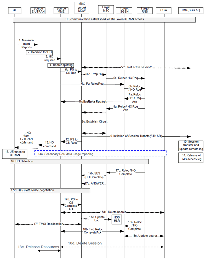
Step 1.

UE sends measurement reports to E-UTRAN.
Step 2.
Based on UE measurement reports and QCI=1 indications, the source E-UTRAN decides to trigger a SRVCC handover to UTRAN.
Step 3.
The source E-UTRAN sends a Handover Required (Target ID, generic Source to Target Transparent Container, SRVCC HO indication) message to the source MME. SRVCC HO indication indicates to MME that this is for CS+PS HO.
Step 4.
If the target is UTRAN, and based on the QCI associated with at least one voice bearer (QCI=1) and at least one vSRVCC marked video bearer, the source MME splits the QCI=1 and vSRVCC marked PS bearer from all other PS bearers and initiates their relocation towards MSC Server and SGSN, respectively.
If the target SGSN uses S4 based interaction with S-GW and P-GW, the PDN Connections IE includes bearer information for the all bearer(s) but the QCI=1 and vSRVCC marked PS bearer. If the target SGSN uses Gn/Gp based interaction with P-GW the Forward Relocation Request will contain PDP Contexts, instead of PDN Connections IE, including bearer information for all bearers but the QCI=1 and vSRVCC marked PS bearers.
Step 5a.
Source MME initiates the PS-CS handover procedure for the QCI=1 and vSRVCC marked PS bearer by sending a SRVCC PS to CS Request (IMSI, Target ID, STN-SR, C-MSISDN, Source to Target Transparent Container, MM Context, vSRVCC indicator) message to the MSC Server. If SRVCC with priority is supported, the MME also includes priority indication in SRVCC PS to CS Request if it detects the SRVCC requires priority handling. The detection is based on the ARP associated with the EPS bearer used for IMS signalling. The priority indication corresponds to the ARP information element. MME received STN-SR, vSRVCC flag and C-MSISDN from the HSS as part of the subscription profile downloaded during the E-UTRAN attach procedure. MM Context contains security related information. CS security key is derived by the MME from the E-UTRAN/EPS domain key as defined in TS 33.401. The CS Security key is sent in the MM Context.
Step 5b1.
When MSC Server receives from the Sv that this is for vSRVCC, it negotiates with the SCC AS to determine if the last active session is voice or voice and video, and execute the CS HO procedure with the appropriate CS resource request with UTRAN. In this call flow, SCC AS indicates voice and video.
Step 5b2.
MSC Server interworks the PS-CS handover request with a CS inter MSC handover request by sending a Prepare Handover Request message to the target MSC. If SRVCC with priority is supported and the MSC Server receives the priority indication (i.e. ARP) in the SRVCC PS to CS Request, the MSC server/MGW sends Prepare Handover Request message to the Target MSC with priority indication mapped from the ARP. The MSC Server maps the ARP to the priority level, pre-emption capability/vulnerability for CS services based on local regulation or operator settings. The priority indication indicates the CS call priority during handover as specified in TS 25.413 for UMTS.
Step 5c.
Target MSC requests BS30 resource allocation for the CS relocation by sending the Relocation Request/Handover Request (additional Source to Target Transparent Container) message to the target RNS. If the MSC Server indicated priority, the RNC/BSS allocates the radio resource based on the existing procedures with priority indication, as specified in TS 23.009 and in TS 25.413 for UMTS.
Step 6.
In parallel to the previous step the source MME initiates relocation of the PS bearers. The following steps are performed (for details see clauses 5.5.2.1 and 5.5.2.3 of TS 23.401):
Step 7.
- Source MME sends a Forward Relocation Request (Source to Target Transparent Container, MM Context, PDN Connections IE) message to the target SGSN. If the target SGSN uses S4 based interaction with S-GW and P-GW, the PDN Connections IE includes bearer information for all bearers except the QCI=1 and vSRVCC marked PS bearers. The handling of security keys for PS handover of the remaining non-QCI=1 and vSRVCC marked PS bearers is specified in TS 33.401.
- Target SGSN requests resource allocation for the PS relocation by sending the Relocation Request/Handover Request (Source to Target Transparent Container) message to the target RNS.
After the target RNS receives both the CS relocation/handover request with the PS relocation/handover request, it assigns the appropriate CS and PS resources. The following steps are performed:
Step 8.
- Target RNS acknowledges the prepared PS relocation/handover by sending the Relocation Request Acknowledge/Handover Request Acknowledge (Target to Source Transparent Container) message to the target SGSN.
- Target SGSN sends a Forward Relocation Response (Target to Source Transparent Container) message to the source MME.
In parallel to the previous step the following steps are performed:
Step 9.
- Target RNS acknowledges the prepared CS relocation/handover by sending the Relocation Request Acknowledge/Handover Request Acknowledge (Target to Source Transparent Container) message to the target MSC.
- Target MSC sends a Prepare Handover Response (Target to Source Transparent Container) message to the MSC Server.
- Establishment of circuit connection between the target MSC and the MGW associated with the MSC Server e.g. using ISUP IAM and ACM messages.
The MSC Server initiates the Session Transfer by using the STN-SR and includes the SDP of the voice and video SDP of the predefined Codecs, which are the default Codecs specified in TS 26.111. If this is a priority session, the MSC Server sends the SIP Session Transfer message with the priority indication to the IMS and the IMS entity handles the session transfer procedure with priority. The priority indication in the SIP Session Transfer message is mapped by the MSC Server from the priority indication (i.e. ARP) in the SRVCC PS to CS Request received in step 5. The mapping of the priority level is based on operator policy and/or local configuration, and the IMS priority indicator should be the same as for the original IMS created over PS.
Step 10.
SCC AS detects based on the presence of the video SDP that it needs to perform a vSRVCC HO. The SCC AS performs a remote leg update with the SDP of the CS access leg for the voice and video session. If the video SDP is missing, the SCC AS assumes a SRVCC HO for voice and initiates the release of the video bearer from the remote leg and the access leg.
Step 11.
SCC AS releases only the source IMS access leg of the voice session according to TS 23.237.
Step 12.
The MSC Server sends a SRVCC PS to CS Response (Target to Source Transparent Container) message to the source MME. The transparent container contains information about the CS bearer reservation.
Step 13.
Source MME synchronises the two prepared relocations and sends a Handover Command (Target to Source Transparent Container) message to the source E-UTRAN.
Step 14.
E-UTRAN sends a Handover from E-UTRAN Command message to the UE. The UE detects the vSRVCC handover.
Step 14a.
If the PLMN has configured Secondary RAT usage data reporting and the source eNodeB has Secondary RAT usage data to report, the reporting is performed as specified in TS 23.401.
Step 15.
UE tunes to the target UTRAN cell.
Step 16.
Handover Detection at the target RNS occurs, then the target RNS sends Handover Detection message to the target MSC. At this stage, the target MSC can send/receive voice data. The UE sends a Handover Complete message via the target RNS to the target MSC. If the target MSC is not the MSC Server, then the Target MSC sends an SES (Handover Complete) message to the MSC Server.
Step 17.
The CS relocation/handover is complete. The following steps are performed:
a)
Step 18)
Target RNS sends Relocation Complete/Handover Complete message to the target MSC.
b)
Target MSC sends an SES (Handover Complete) message to the MSC Server. The speech circuit is through connected in the MSC Server/MGW according to TS 23.009.
c)
Completion of the establishment procedure with ISUP Answer message to the MSC Server according to TS 23.009.
c1)
Predefined Codecs for voice and video as specified in TS 26.111 are initially used by the UE after it has established the circuit bearer to the target MSC. After that, the UE may start the 3G-324M codec negotiation for video (refer to TR 26.911 and ITU-T Recommendation H.324 [33], Annex K for H.245 signalling optimizations) if needed.
d)
MSC Server sends a SRVCC PS to CS Complete Notification message to the source MME. Source MME acknowledges the information by sending a SRVCC PS to CS Complete Acknowledge message to the MSC Server.
d1)
The source MME deactivates the QCI=1 and vSRVCC marked PS bearers towards S-GW/P-GW and sets the PS-to-CS handover indicator to Delete Bearer Command message. If dynamic PCC is deployed, the PGW may interact with PCRF as defined in TS 23.203.
e)
If IMSI is unknown in the VLR, the MSC Server performs a MAP Update Location to the HSS/HLR.
f)
If the MSC Server performed a MAP Update location in step 17e and if multiple MSC/VLRs serve the same LAI, the MSC Server performs a TMSI reallocation towards the UE using a non-broadcast LAI with its own Network Resource Identifier (NRI).
In parallel to the previous step, the PS relocation/handover is completed. The following steps are performed:
- Target RNS sends Relocation Complete/Handover Complete message to target SGSN.
- Target SGSN sends a Forward Relocation Complete message to the source MME. Source MME acknowledges the information by sending a Forward Relocation Complete Acknowledge message to the target SGSN.
- Target SGSN updates the bearer with S-GW/P-GW as specified in TS 23.401.
- The source MME sends Delete Session Request to the SGW as defined in TS 23.401.
- The source MME requests the release of the resources, including release of the S1 signalling connection, to the Source eNodeB as defined in TS 23.401. The Source eNodeB releases its resources related to the UE and responds back to the MME.
6.2.2.4 vSRVCC from E-UTRAN to UTRAN without PS HO support |R11| p. 52
The call flow for this scenario is similar to the call flow depicted in Figure 6.2.2.3-1, with the exceptions that the PS HO procedure (step 6 and 7) is not performed. The scenario requires that E-UTRAN can determine that the target is UTRAN (HSPA) without PS HO support. The message in step 3 in Figure 6.2.2.1-1 includes an indication to the MME that the UE is available for PS service in the target cell. At the end of the procedure, the UE re-establishes the PS resources by performing the Routeing Area Update procedure as described in TS 23.060 and in TS 23.401.
6.2.3 Returning back to E-UTRAN |R12| p. 52
Once CS service ends in CS domain, existing mechanisms as specified in TS 23.401 and TS 23.060 can be used to move the UE to E-UTRAN e.g. by prioritizing E-UTRAN over GERAN/UTRAN.
When configured to support the return to E-UTRAN after SRVCC, the MSC shall indicate this to GERAN/UTRAN during the release of an RR connection that was established for SRVCC, e.g. by indicating the last used E-UTRAN PLMN. GERAN and UTRAN may use the indication from the MSC to determine which of the existing mechanisms that should be used to move the UE to E-UTRAN, see also TS 23.272.
![]()
![]()
![]()