Content for TS 23.216 Word version: 18.0.0
6.3.2.2 SRVCC from UTRAN (HSPA) to UTRAN or GERAN with DTM HO support p. 57
Depicted in Figure 6.3.2.2-1 is a call flow for SRVCC from UTRAN (HSPA) to UTRAN or GERAN with DTM HO support, including the handling of the non-voice component.
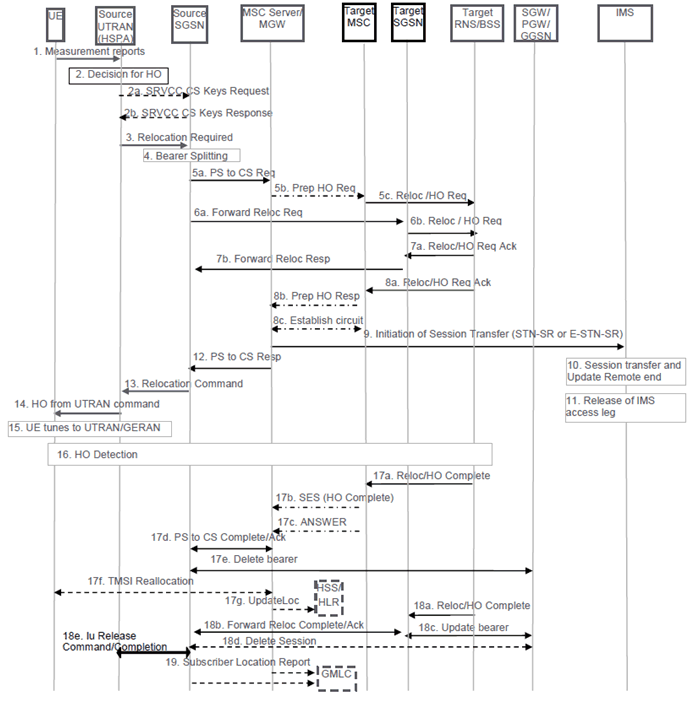
Figure 6.3.2.2-1: SRVCC from UTRAN (HSPA) to UTRAN or GERAN with DTM HO support
(⇒ copy of original 3GPP image)
(⇒ copy of original 3GPP image)
Step 1.
If the SGSN determines that only the relocation of the voice bearer but not the relocation of one or more PS bearers succeeds, then the SGSN proceeds step13 after receiving SRVCC PS to CS Response from the MSC Server in step 12 and both UE and SGSN continue the procedure described in clause 6.3.2.1A.
UE sends measurement reports to Source UTRAN (HSPA).
Step 2.
Based on UE measurement reports the source UTRAN (HSPA) decides to trigger a handover to UTRAN/GERAN.
Step 2a.
In the case of SRVCC to UTRAN the RNC shall initiate the SRVCC Preparation procedure by sending an SRVCC CS KEYS REQUEST message to the source SGSN.
Step 2b.
The SGSN shall respond to the RNC with SRVCC CS KEYS RESPONSE message containing the Integrity Protection Key IE, the Encryption Key IE and the SRVCC Information IE.
Step 3.
If target is UTRAN, the source UTRAN (HSPA) sends a Relocation Required (Target ID, Source RNC to Target RNC Transparent Container, SRVCC Handover Indication) message to the source SGSN. UTRAN (HSPA) also indicates to SGSN that this is for CS+PS HO.
If target is GERAN, the source UTRAN (HSPA) sends a Relocation Required (Target ID, Old BSS to New BSS Information IE for the CS domain and Source BSS to Target BSS Transparent Container for the PS Domain, SRVCC Handover Indication) message to the source SGSN. The differentiation between CS and PS containers is described in TS 25.413. In this case, the SGSN identifies from the SRVCC Handover Indication that this is a request for a CS+PS handover.
Step 4.
Based on the Traffic Class associated with conversational and Source Statistic Descriptor = speech, and the SRVCC Handover Indication the Source SGSN splits the voice bearer from all other PS bearers and initiates their relocation towards MSC Server and SGSN, respectively.
Step 5a.
Source SGSN initiates the PS-CS handover procedure for the voice bearer by sending a SRVCC PS to CS Request (IMSI, Target ID, STN-SR, C-MSISDN, Source to Target Transparent Container, MM Context, Emergency Indication, Source SAI) message to the MSC Server. The Emergency Indication and the equipment identifier are included if the ongoing session is emergency session. Authenticated IMSI and C-MSISDN shall be included if available. The message includes information relevant to the CS domain only. SGSN received STN-SR and C-MSISDN from the HSS as part of the subscription profile downloaded during the UTRAN (HSPA) attach procedure. MM Context contains security related information. The CS Security key is derived by the SGSN from the UTRAN (HSPA)/EPS domain key as defined in TS 33.102. If the target system is GERAN, the Source SAI shall be set to the Serving Area Identifier received from the source RNC.
Step 5b.
MSC Server interworks the PS handover request with a CS inter-MSC handover request by sending a Prepare Handover Request message to the target MSC. If the target system is GERAN, MSC Server uses BSSMAP encapsulated for the Prepare Handover Request. If the target system is UTRAN, MSC Server uses RANAP encapsulated for the Prepare Handover Request.
Step 5c.
Target MSC requests resource allocation for the CS relocation by sending the Relocation Request/Handover Request (Source to Target Transparent Container) message to the target RNS/BSS.
Step 6.
In parallel to the previous step the source SGSN initiates relocation of the PS bearers. The following steps are performed (for details see TS 23.060):
Step 7.
- If the target SGSN uses S4 based interaction with S-GW and P-GW, the source SGSN sends a Forward Relocation Request (Source to Target Transparent Container, MM Context, PDP Context) message to the target SGSN. The PDP Context includes bearer information for all bearers except the voice bearer. The handling of security keys for PS handover of the remaining non-voice PS bearers is specified in TS 33.401. If the target SGSN uses Gn/Gp based interaction with GGSN, the Source SGSN sends a Forward Relocation Request (Source to Target Transparent Container, MM Context and PDP Context) message to the target SGSN. The PDP Context includes bearer information for all bearers except the voice bearer. The handling of security keys for PS handover of the remaining non-voice PS bearers is specified in TS 33.102.
- Target SGSN requests resource allocation for the PS relocation by sending the Relocation Request/Handover Request (Source to Target Transparent Container) message to the target RNS/BSS.
Target RNS/BSS coordinates the CS relocation request with the PS relocation request and assigns resources. The following steps are performed:
Step 8.
- Target RNS/BSS acknowledges the prepared PS relocation by sending the Relocation Request Acknowledge/Handover Request Acknowledge (Target to Source Transparent Container) message to the target SGSN.
- Target SGSN sends a Forward Relocation Response (Target to Source Transparent Container) message to the source SGSN.
In parallel to the previous step the following steps are performed:
Step 9.
- Target RNS/BSS acknowledges the prepared CS relocation by sending the Relocation Request Acknowledge/Handover Request Acknowledge (Target to Source Transparent Container) message to the target MSC.
- Target MSC sends a Prepare Handover Response (Target to Source Transparent Container) message to the MSC Server.
- Establishment of circuit connection between the target MSC and the MGW associated with the MSC Server e.g. using ISUP IAM and ACM messages.
For non-emergency session, the MSC Server initiates the Session Transfer by using the STN-SR e.g. by sending an ISUP IAM (STN-SR) message towards the IMS. For emergency session, the MSC Server initiates the Session Transfer by using the locally-configured E-STN-SR and by including the equipment identifier. Standard IMS Service Continuity or Emergency IMS Service Continuity procedures are applied for execution of the Session Transfer, see TS 23.237.
Step 10.
During the execution of the Session Transfer procedure the remote end is updated with the SDP of the CS access leg according to TS 23.237. The downlink flow of VoIP packets is switched towards the CS access leg at this point.
Step 11.
The source IMS access leg is released according to TS 23.237.
Step 12.
The MSC Server sends a SRVCC PS to CS Response (Target to Source Transparent Container) message to the source SGSN.
Step 13.
Source SGSN synchronises the two prepared relocations and sends a Relocation Command (Target to Source Transparent Container) message to the source UTRAN (HSPA). If the target is GERAN, the source RNC shall receive the SRVCC Information IE containing the NONCE IE.
Step 14.
UE tunes to the target UTRAN/GERAN cell.
Step 15.
UTRAN (HSPA) sends a Handover Command message to the UE.
Step 16.
Handover Detection at the target RNS/BSS, then the target RNS/BSS sends Handover Detection message to the target MSC. At this stage, the target MSC can send/receive voice data. The UE sends a Handover Complete message via the target RNS/BSS to the target MSC.
Step 17.
The CS relocation is complete. The following steps are performed:
Step 18.
- Target RNS/BSS sends Relocation Complete/Handover Complete message to the target MSC.
- Target MSC sends an SES (Handover Complete) message to the MSC Server. The speech circuit is through connected in the MSC Server/MGW according to TS 23.009.
- Completion of the establishment procedure with ISUP Answer message to the MSC Server according to TS 23.009.
- MSC Server sends a SRVCC PS to CS Complete Notification message to the source SGSN. Source SGSN acknowledges the information by sending a SRVCC PS to CS Complete Acknowledge message to the MSC Server.
- The source SGSN deletes the voice bearer towards GGSN/S-GW/P-GW and sets the PS-to-CS handover indicator. If dynamic PCC is deployed, the PGW may interact with PCRF as defined in TS 23.203.
- For non-emergency sessions if the HLR is to be updated, i.e. if the IMSI is authenticated but unknown in the VLR, the MSC Server performs a TMSI reallocation towards the UE using its own non-broadcast LAI and, if the MSC Server and other MSC/VLRs serve the same (target) LAI, with its own Network Resource Identifier (NRI).
- For non-emergency sessions if the MSC Server performed a TMSI reallocation in step 17f, and if this TMSI reallocation was completed successfully, the MSC Server performs a MAP Update Location to the HSS/HLR.
In parallel to the previous step, the PS relocation is complete. The following steps are performed:
Step 19.
- Target RNS/BSS sends Relocation Complete/Handover Complete message to target SGSN.
- Target SGSN sends a Forward Relocation Complete message to the source SGSN. After having completed step 17e, source SGSN acknowledges the information by sending a Forward Relocation Complete Acknowledge message to the target SGSN.
- Target SGSN updates the bearer with GGSN/S-GW/P-GW.
- The Source S4-SGSN sends delete Session Request to the SGW as defined in TS 23.401.
- The source SGSN sends a Iu Release Command to the Source RNC. The Source RNC releases its resources related to the UE and responds with an Iu Release Complete message.
For an emergency services session after handover is complete, the source SGSN or the MSC Server may send a Subscriber Location Report carrying the identity of the MSC Server to a GMLC associated with the source or target side, respectively, as defined in TS 23.271 to support location continuity.
![]()
![]()
![]()