Content for TS 23.009 Word version: 18.0.0
1…
4…
4.3…
6…
6.2…
6.2.3
6.3…
7…
7.2…
8…
8.1.3…
8.2…
8.2.2…
8.2.4
8.3…
8.3.2…
9…
10…
11…
12…
12.8…
12.8.2
12.8.3
13…
14…
15…
8.3.2 Basic relocation procedure not requiring the establishment of a circuit connection between 3G_MSC-A and 3G_MSC-B
8.3.3 Procedure for subsequent relocation requiring a circuit connection
8.3.4 Procedure for subsequent relocation not requiring a circuit connection
...
...
8.3.2 Basic relocation procedure not requiring the establishment of a circuit connection between 3G_MSC-A and 3G_MSC-B p. 76
The basic SRNS relocation procedures to be used when no circuit connection is required by 3G_MSC-A are similar to those described in subclause 8.3.1 for circuit switched calls. The main differences to the procedures described in subclause 8.3.1 relate to the establishment of circuits between the network entities and the Handover Number allocation.
In the case of basic relocation, 3G_MSC-A shall specify to 3G_MSC-B that no Handover Number is required in the MAP-PREPARE-HANDOVER request (see TS 29.002). As for the basic relocation using a circuit connection, the IU-RELOC-REQUEST is transmitted at the same time together with the identity of the target RNS to which the call is to be relocated. Any subsequent Handover Number allocation procedure will not be invoked until the completion of the basic relocation procedure (see clause: Subsequent Channel Assignment using a circuit connection). 3G_MSC-B shall then perform the radio resources allocation as described in subclause 8.3.1 if applicable. The MAP-PREPARE-HANDOVER response shall be returned to 3G_MSC-A including either the response of the radio resources allocation request received from RNS-B (IU-RELOC-REQUEST-ACKNOWLEDGE/IU-RELOC-FAILURE with possible extra RANAP information. This extra information is amended by 3G_MSC-B due to the possible interworking between the RANMAP protocol carried on the E-interface and the RANAP protocol used on the Iu-interface). The basic relocation procedure will continue as described in subclause 8.3.1 except that no circuit connection will be established towards 3G_MSC-B.
The relevant case for the basic relocation without circuit connection is shown in Figure 31. As can be seen the major differences to the equivalent Figure 30 are the omission of any circuit establishment messaging and the omission of handover number allocation signalling.
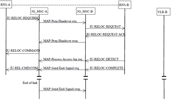
Figure 31: Basic SRNS relocation procedure without a circuit connection
(⇒ copy of original 3GPP image)
(⇒ copy of original 3GPP image)
8.3.3 Procedure for subsequent relocation requiring a circuit connection p. 77
After the call has been relocated to 3G_MSC-B, if the UE leaves the area of 3G_MSC-B during the same call, subsequent relocation is necessary in order to continue the connection when no Iur interface exists between the involved RNSs, or to optimise the transmission path when the Iur interface is used.
The following cases apply:
- the UE moves back to the area of 3G_MSC-A;
- the UE moves into the area of a third 3G_MSC (3G_MSC-B').
8.3.3.1 Description of subsequent relocation procedure i): 3G_MSC-B to 3G_MSC-A p. 78
The procedure for successful relocation from 3G_MSC-B back to 3G_MSC-A is shown in Figure 32.
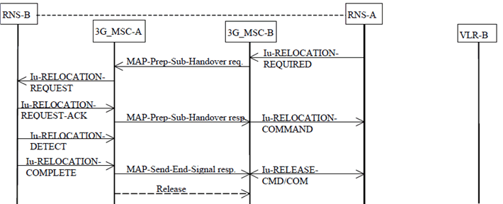
Figure 32: Subsequent relocation procedure i) successful relocation from 3G_MSC-B to 3G_MSC-A using a circuit connection
(⇒ copy of original 3GPP image)
(⇒ copy of original 3GPP image)
8.3.3.1.1 With one circuit connection p. 78
The procedure is as follows.
If 3G_MSC-B supports SRNS Relocation to a CSG cell, 3G_MSC-A provided CSG subscription data during the basic inter-MSC handover/relocation, and RNS-A includes a CSG ID for the target cell in the IU-RELOCATION-REQUIRED message, then 3G_MSC-B shall check the CSG membership of the UE for the target cell as described in subclause 4.4.1 before generating the MAP-PREPARE-SUBSEQUENT-HANDOVER request. If the UE fails the CSG membership check and the target cell is a CSG cell, 3G_MSC-B shall send an IU-RELOCATION-PREPARATION-FAILURE message to RNS-A.
3G_MSC-B sends the MAP-PREPARE-SUBSEQUENT-HANDOVER request to 3G_MSC-A indicating the new 3G_MSC number (3G_MSC-A number), indicating also the identity of the target RNS where the call has to be relocated and including a complete IU-RELOC-REQUEST message.
For speech calls, 3G_MSC-B shall configure the RANAP RAB parameters according to the appropriate default speech codec. For a relocation to UTRAN Iu mode, if this codec is different from the Iu Currently used codec, 3G_MSC-B shall also include the NAS Synch Indicator for the default speech codec in the Iu-RELOCATION-REQUEST.
Alternatively, if 3G_MSC-A is known to support the use of the Iu Supported Codecs List, 3G_MSC-B may configure the RANAP RAB parameters according to the preferred codec and indicate this to 3G_MSC-A by including the RAB configuration indicator in the MAP-PREPARE-SUBSEQUENT-HANDOVER request. For a relocation to UTRAN Iu mode, if the preferred codec is different from the Iu Currently used codec, 3G_MSC-B shall also include the NAS Synch Indicator for the preferred codec in the Iu-RELOCATION-REQUEST.
Since 3G_MSC-A is the call controlling 3G_MSC, this 3G_MSC needs no Handover Number for routing purposes; 3G_MSC-A can immediately initiate the relocation towards the target RNS.
For speech calls, 3G_MSC-A shall select an Iu Selected codec and connect a transcoder.
3G_MSC-A shall reconfigure the RANAP RAB parameters according to the Iu Selected codec:
- if the RAB configuration indicator is included in the MAP-PREPARE-SUBSEQUENT-HANDOVER request, and the codec selected by 3G_MSC-A is different from the preferred codec; or
- if the RAB configuration indicator is not included in the MAP-PREPARE-SUBSEQUENT-HANDOVER request and the codec selected by 3G_MSC-A is different from the appropriate default speech codec.
8.3.3.1.2 With multiple circuit connections (Optional functionality) p. 79
If 3G_MSC-A and 3G_MSC_B support the optional supplementary service Multicall (See TS 23.135), 3G_MSC-A and 3G_MSC-B shall have the following functionality additionally to the description in subclause 8.3.3.1.1.
Upon receipt of the IU-RELOCATION-REQUIRED from RNS-A, 3G_MSC-B generates IU-RELOCATION-REQUEST which may include several bearers and sends it to 3G_MSC-A over MAP-PREPARE-SUBSEQUENT-HANDOVER request.
3G_MSC-A sends IU-RELOCATION-REQUEST to RNS-B and receives IU-RELOCATION-REQUEST-ACK.
When MAP-PREPARE-SUBSEQUENT-HANDOVER response is received from 3G_MSC-A, 3G_MSC-B sends IU-RELOCATION-COMMAND, which indicates the bearers failed to set up in RNS-B as bearers to be released, to RNS-A.
After 3G_MSC-A receives IU-RELOCATION-COMPLETE message from RNS-B, 3G_MSC-A shall release calls via RNS-B, which has been carried by the bearers failed to set up in RNS-B, and then 3G_MSC-A sends MAP-SEND-END-SIGNAL response to 3G_MSC-B.
8.3.3.2 Description of subsequent relocation procedure ii): 3G_MSC-B to 3G_MSC-B' p. 79
The procedure for successful relocation from 3G_MSC-B to 3G_MSC-B' is shown in Figure 33.
The procedure consists of two parts:
- a subsequent relocation from 3G_MSC-B back to 3G_MSC-A as described in subclause 8.3.3.1; and
- a basic relocation from 3G_MSC-A to 3G_MSC-B' as described in subclause 8.3.1.
8.3.3.2.1 With one circuit connection p. 79
If 3G_MSC-B supports SRNS Relocation to a CSG cell and RNS-A includes a CSG ID for the target cell in the IU-RELOCATION-REQUIRED message, then 3G_MSC-B shall check the CSG membership of the UE for the target cell as described in subclause 8.3.3.1.1 before initiating the procedure, and reject the handover if necessary.
3G_MSC-B sends the MAP-PREPARE-SUBSEQUENT-HANDOVER request to 3G_MSC-A indicating a new 3G_MSC number (which is the identity of 3G_MSC-B'), indicating also the target RNS identity and including a complete IU-RELOC-REQUEST, 3G_MSC-A then starts a basic relocation procedure towards 3G_MSC-B'.
For speech calls, 3G_MSC-B shall configure the RANAP RAB parameters according to the appropriate default speech codec. For a relocation to UTRAN Iu mode, if this codec is different from the Iu Currently used codec, 3G_MSC-B shall also include the NAS Synch Indicator for the default speech codec in the Iu-RELOCATION-REQUEST.
Alternatively, if 3G_MSC-A and 3G_MSC-B' are known to support the use of the Iu Supported Codecs List, 3G_MSC-B may configure the RANAP RAB parameters according to the preferred codec and indicate this to 3G_MSC-A by including the RAB configuration indicator in the MAP-PREPARE-SUBSEQUENT-HANDOVER request. For a relocation to UTRAN Iu mode, if the preferred codec is different from the Iu Currently used codec, 3G_MSC-B shall also include the NAS Synch Indicator for the preferred codec in the Iu-RELOCATION-REQUEST. The decision to use this option is based on internal configuration information in 3G_MSC-B.
If 3G_MSC-A supports A interface over IP, then for speech calls 3G_MSC-A may include the AoIP-Supported Codecs List (Anchor) in the MAP-PREPARE-HANDOVER request towards 3G_MSC-B'. For a detailed description of the handling of this codec list by 3G_MSC-A and 3G_MSC-B' see TS 23.153.
When 3G_MSC-A receives the ACM from 3G_MSC-B', 3G_MSC-A informs 3G_MSC-B that 3G_MSC-B' has successfully allocated the radio resources on RNS-B' side by sending the MAP-PREPARE-SUBSEQUENT-HANDOVER response containing the complete IU-RELOC-REQUEST-ACKNOWLEDGE received from RNS-B' and possible extra RANAP information, amended by 3G_MSC-A due to the possible interworking between the RANAP protocol carried on the E-interface between 3G_MSC-A and 3G_MSC-B' and the RANAP protocol carried on the E interface between 3G_MSC-A and 3G_MSC-B. Now 3G_MSC-B can start the procedure on the radio path if needed.
For 3G_MSC-A the relocation is completed when it has received the MAP-SEND-END-SIGNAL REQUEST from 3G_MSC-B'containing the IU-RELOC-COMPLETE received from the RNS-B'. The circuit between 3G_MSC-A and 3G_MSC-B is released. 3G_MSC-A also sends the MAP-SEND-END-SIGNAL response to 3G_MSC-B in order to terminate the original MAP dialogue between 3G_MSC-A and 3G_MSC-B. 3G_MSC-B releases the radio resources when it receives this message.
If no radio resource can be allocated by 3G_MSC-B' or no circuit between 3G_MSC-A and 3G_MSC-B' can be established or a fault is detected on the target RNS identity or the target RNS identity in the IU-RELOC-REQUEST is not consistent with the target 3G_MSC number, 3G_MSC-A informs 3G_MSC-B by using the IU-RELOC-FAILURE message included in the MAP-PREPARE-SUBSEQUENT-HANDOVER response. 3G_MSC-B shall maintain the existing connection with the UE.
When the subsequent relocation is completed, 3G_MSC-B' is considered as 3G_MSC-B. Any further inter-3G_MSC relocation is handled as described above for a subsequent relocation.
8.3.3.2.2 With multiple circuit connections (Optional functionality) p. 80
If 3G_MSC-A and 3G_MSC-B support the optional supplementary service Multicall (See TS 23.135), 3G_MSC-A and 3G_MSC-B shall have the following functionality additionally to the description in subclause 8.3.3.2.1.
Upon receipt of the IU-RELOCATION-REQUIRED from RNS-B 3G_MSC-B generates an IU-RELOCATION-REQUEST message which may include multiple bearer and sends it to 3G_MSC-A over MAP-PREPARE-SUBSEQUENT-HANDOVER request.
Upon receipt of the MAP-PREPARE-SUBSEQUENT-HANDOVER request from 3G_MSC-B, 3G_MSC-A starts a basic relocation procedure towards 3G_MSC-B'.
8.3.3.2.2.1 3G_MSC-B' does not support multiple bearers p. 80
If 3G_MSC-A receives an indication that 3G_MSC-B' does not support multiple bearers, 3G_MSC-A shall select one bearer to be handed over. 3G_MSC-A reconstructs IU-RELOCATION-REQUEST and sends again a MAP-PREPARE-HANDOVER request to 3G_MSC-B' including the IU-RELOCATION-REQUEST message, which includes only the selected bearer. Upon receipt of MAP-PREPARE-HANDOVER response from 3G_MSC-B', 3G_MSC-A shall reconstructs IU-RELOCATION-REQUEST-ACK to indicate the bearers not to be handed over as the bearers failed to set up in IU-RELOCATION-REQUEST-ACK and send it over MAP-PREPARE-SUBSEQUENT-HANDOVER response to 3G_MSC-B.
When MAP-PREPARE-SUBSEQUENT-HANDOVER response is received from 3G_MSC-A 3G_MSC-B sends IU-RELOCATION-COMMAND, which indicates the bearers failed to set up as bearers to be released, to RNS-A.
After 3G_MSC-A receives MAP-SEND-END-SIGNAL request from 3G_MSC-B', 3G_MSC-A shall release calls via 3G_MSC-B', which has been carried by the bearers failed to set up, and then 3G_MSC-A sends MAP-SEND-END-SIGNAL response to 3G_MSC-B.
8.3.3.2.2.2 3G_MSC-B' supports multiple bearers p. 81
If some of circuit connections failed to set up between 3G_MSC-A and 3G_MSC-B', 3G_MSC-A shall reconstruct IU-RELOCATION-REQUEST-ACK message so that the IU-RELOCATION-REQUEST-ACK includes only the bearers which have successfully established circuit connection and sends it to 3G_MSC-B over MAP-PREPARE-SUBSEQUENT-HANDOVER response.
When MAP-PREPARE-SUBSEQUENT-HANDOVER response is received from 3G_MSC-A 3G_MSC-B sends IU-RELOCATION-COMMAND, which indicates the bearers failed to set up as bearers to be released, to RNS-A.
After 3G_MSC-A receives MAP-SEND-END-SIGNAL request from 3G_MSC-B', 3G_MSC-A shall release calls via 3G_MSC-B', which has been carried by the bearers failed to set up, and then 3G_MSC-A sends MAP-SEND-END-SIGNAL response to 3G_MSC-B.
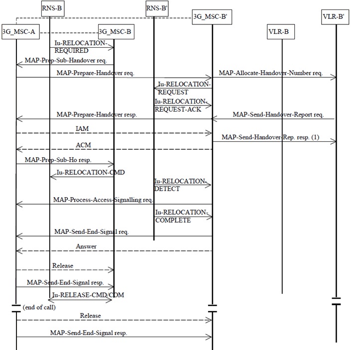
Figure 33: Subsequent relocation procedure ii) Successful SRNS relocation from 3G_MSC-B to 3G_MSC-B' requiring a circuit connection
(⇒ copy of original 3GPP image)
(⇒ copy of original 3GPP image)
8.3.4 Procedure for subsequent relocation not requiring a circuit connection p. 82
As for the subsequent relocation with a circuit connection between 3G_MSC-A and 3G_MSC-B, the same two cases of subsequent relocation apply:
- the UE moves back to the area of 3G_MSC-A;
- the UE moves into the area of a third 3G_MSC (3G_MSC-B').
8.3.4.1 Description of subsequent relocation procedure i): 3G_MSC-B to 3G_MSC-A p. 83
The procedure for successful relocation from 3G_MSC-B back to 3G_MSC-A without circuit connection is shown in Figure 34. The only difference with the Figure 32 is that no circuit release is needed between 3G_MSC-A and 3G_MSC-B.
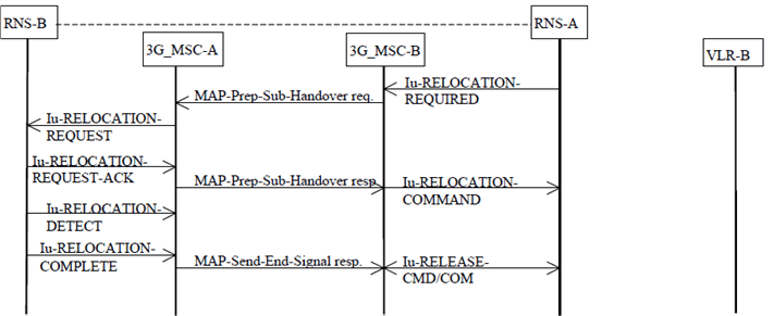
Figure 34: Subsequent relocation procedure i) successful relocation from 3G_MSC-B to 3G_MSC-B not requiring a circuit connection
(⇒ copy of original 3GPP image)
(⇒ copy of original 3GPP image)
8.3.4.2 Description of subsequent relocation procedure ii): 3G_MSC-B to 3G_MSC-B'' p. 83
The procedure for successful relocation from 3G_MSC-B to 3G_MSC-B' is shown in Figure 35.
The procedure consists of two parts:
- a subsequent relocation from 3G_MSC-B back to 3G_MSC-A as described in subclause 8.3.4.1; and
- a basic relocation from 3G_MSC-A to 3G_MSC-B' as described in subclause 8.3.2.
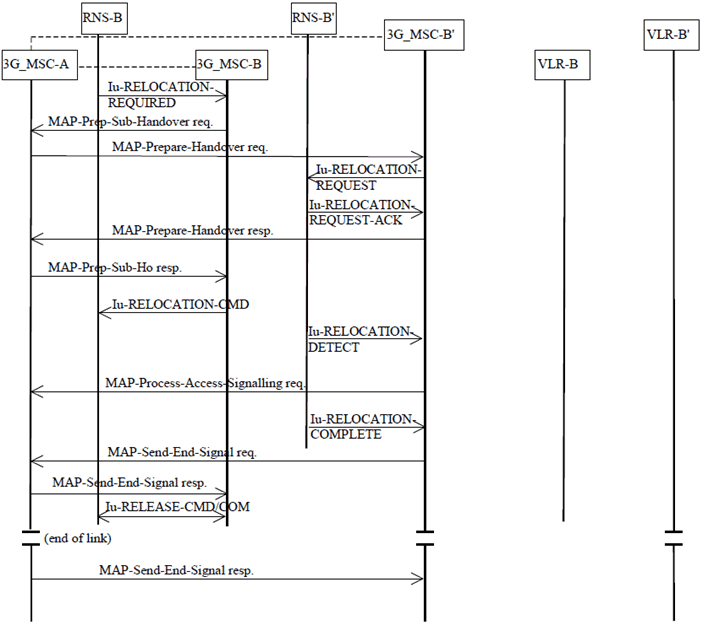
Figure 35: Subsequent relocation procedure ii) Successful SRNS relocation from 3G_MSC-B to 3G_MSC-B' not requiring a circuit connection
(⇒ copy of original 3GPP image)
(⇒ copy of original 3GPP image)
![]()
![]()
![]()