Content for TS 23.009 Word version: 18.0.0
1…
4…
4.3…
6…
6.2…
6.2.3
6.3…
7…
7.2…
8…
8.1.3…
8.2…
8.2.2…
8.2.4
8.3…
8.3.2…
9…
10…
11…
12…
12.8…
12.8.2
12.8.3
13…
14…
15…
8.3 SRNS Relocation
8.3.1 Basic relocation procedure requiring a circuit connection between 3G_MSC-A and 3G_MSC-B
...
...
8.3 SRNS Relocation p. 71
The following clauses describe two options for the Basic and Subsequent Relocation procedures. The first, as described in subclauses 8.3.1 and 8.3.3 respectively, provides for a circuit connection between 3G_MSC-A and 3G_MSC-B. The second, as described in subclauses 8.3.2 and 8.3.4 respectively, provides for a Basic and Subsequent Relocation without the provision of a circuit connection between 3G_MSC-A and 3G_MSC-B.
In all the above mentioned clauses, the following principles apply:
- during the relocation resource allocation, except for the messages explicitly indicated in b and c below, only the relocation related messages that are part of the applicable RANAP subset - as defined in TS 29.108 - shall be transferred on the E-interface;
- the trace related messages that are part of the applicable RANAP subset - as defined in TS 29.108 - can be sent by the 3G_MSC-A on the E-interface after successful relocation resource allocation. In the clauses 8.3.1 and 8.3.2, it is however allowed at basic relocation initiation on the E-Interface to transfer one trace invocation related message that is part of the applicable RANAP subset - as defined in TS 29.108 - together with the applicable relocation related message. The applicable relocation related message shall always appear as the first message;
- during the relocation resource allocation for subsequent inter-MSC SRNS relocation according to subclauses 8.3.3 and 8.3.4, it is allowed to transfer either DTAP or RANAP Direct Transfer messages on the E-Interface between 3G_MSC-A and 3G_MSC-B. RANAP Direct Transfer messages shall be used for this purpose if and only if the basic handover procedure was an inter MSC SRNS relocation;
- the Iu-Location Reporting Control message which belongs to the applicable RANAP subset - as defined in TS 29.108 - can be sent by the 3G_MSC-A on the E-interface after successful relocation resource allocation;
- during the relocation execution, i.e. while the UE is not in communication with the network, the 3G_MSC-A shall queue all outgoing RANAP or BSSAP messages until the communication with the UE is resumed;
- during the execution of a basic inter-MSC SRNS relocation to 3G_MSC-B or a subsequent inter-MSC SRNS relocation to a third 3G-MSC-B', only the relocation related messages and the Iu-Release-Request message that are part of the applicable RANAP subset - as defined in TS 29.108 - may be sent by the target MSC on the E-interface;
- during a subsequent inter-MSC SRNS relocation back to 3G_MSC-A or to a third 3G_MSC-B', 3G_MSC-B may initiate either an Iu-Release-Request procedure or an A-Clear-Request procedure on the E-interface. An Iu-Release-Request procedure shall be initiated only if the basic handover procedure was an inter-MSC SRNS relocation;
- finally, during supervision, i.e. while the UE is not in the area of 3G_MSC-A after a successful Inter-3G_MSC relocation, the subset of RANAP procedures and their related messages - as defined in TS 29.108 - shall apply on the E-Interface. As an exception to this rule, 3G_MSC-B shall notify 3G_MSC-A of a successfully completed subsequent intra-MSC-B intra GSM or inter-system handover by using the Internal Handover Indication procedure as specified in TS 49.008. Furthermore, in case of a subsequent inter-MSC intra GSM or inter-system handover back to 3G_MSC-A or to a third 3G_MSC-B', during the handover resource allocation, the handover and trace related messages that are part of the applicable BSSAP subset - as defined in TS 49.008 - shall be transferred on the E-interface (see list items a and b in clause 7, subclauses 8.1 and 8.2, respectively). If a subsequent inter-MSC handover/relocation back to 3G_MSC-A or to a third 3G_MSC-B' is cancelled, then the supervision continues, and RANAP procedures and their related messages shall apply on the E-interface.
- during the intra-3G_MSC-B relocation execution, if any, the 3G_MSC-B shall queue all outgoing RANAP messages until the communication with the UE is resumed.
- after successful completion of the Intra-3G_MSC-B relocation, if 3G_MSC-B or 3G-MSC-B' has previously received an order to perform location reporting at change of Service Area from 3G_MSC-A, it shall act as specified in subclause 6.2.3.
8.3.1 Basic relocation procedure requiring a circuit connection between 3G_MSC-A and 3G_MSC-B p. 72
The procedure used for successful Inter-3G_MSC SRNS relocation is shown in Figure 30. Initiation of the relocation procedure is described in clause 5. The procedure described in this clause makes use of messages from the TS 25.413 and of the transport mechanism from the Mobile Application Part (MAP) (TS 29.002). After an Inter-3G_MSC SRNS relocation further Intra-3G_MSC relocations may occur on 3G_MSC-B, these relocations will follow the procedures specified in a previous clause.
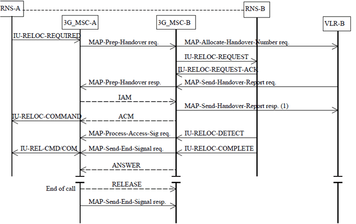
Figure 30: Basic SRNS Relocation Procedure requiring a circuit connection
(⇒ copy of original 3GPP image)
(⇒ copy of original 3GPP image)
8.3.1.1 With one circuit connection p. 73
The relocation is initiated as described in subclause 6.2.3. (This is represented by IU-RELOC-REQUIRED in Figure 30). Upon receipt of the IU-RELOC-REQUIRED from RNS-A, 3G_MSC-A shall send a MAP-PREPARE-HANDOVER request to 3G_MSC-B including a complete IU-RELOC-REQUEST message. (NOTE: 3G_MSC-A shall not send further MAP-PREPARE-HANDOVER requests while a MAP-PREPARE-HANDOVER response is pending or before any timeouts). The MAP-PREPARE-HANDOVER request shall carry in the IU-RELOC-REQUEST all information needed by 3G_MSC-B for allocating radio resources in the case of SRNS relocation without Iur interface, see TS 25.413.
For speech calls, 3G_MSC-A shall include the Iu Currently used codec and the Iu Supported Codecs List in the MAP-PREPARE-HANDOVER request. 3G_MSC-A shall configure the RANAP RAB parameters according to the appropriate default speech codec. For a relocation to UTRAN Iu mode, if this codec is different from the Iu Currently used codec, 3G_MSC-A shall also include the NAS Synch Indicator for the default speech codec in the Iu-RELOCATION-REQUEST.
Alternatively, if 3G_MSC-B is known to support the use of the Iu Supported Codecs List, 3G_MSC-A may configure the RANAP RAB parameters according to the preferred codec and indicate this to 3G_MSC-B by including the RAB configuration indicator in the MAP-PREPARE-HANDOVER request. For a relocation to UTRAN Iu mode, if the preferred codec is different from the Iu Currently used codec, 3G_MSC-A shall also include the NAS Synch Indicator for the preferred codec in the Iu-RELOCATION-REQUEST. The decision to use this option is based on internal configuration information in 3G_MSC-A.
MAP-PREPARE-HANDOVER request shall also carry the identity of the target RNS to which the call is to be relocated, see TS 29.002.
If 3G_MSC-A supports SRNS Relocation to a CSG cell and RNS-A includes a CSG ID for the target cell in the IU-RELOCATION-REQUIRED message, then 3G_MSC-A shall check the CSG membership of the UE for the target cell as described in subclause 4.3.1 before generating the MAP-PREPARE-HANDOVER request. If the UE fails the CSG membership check and the target cell is a CSG cell, 3G_MSC-A shall send an IU-RELOCATION-PREPARATION-FAILURE to RNS-A.
If 3G_MSC-A supports SRNS Relocation to a CSG cell, the target cell belongs to the registered PLMN or an equivalent PLMN, and the HLR or the CSS provided CSG subscription data, 3G_MSC-A shall include the CSG subscription data for the registered PLMN and, if available, for the equivalent PLMNs in the MAP-PREPARE-HANDOVER request.
3G_MSC-B will return the MAP-PREPARE-HANDOVER response after having retrieved one or several Handover Numbers from its associated VLR (exchange of the messages MAP-allocate-handover-number request and MAP-send-handover-report request). The Handover Numbers shall be used for routing the connections of the calls from 3G_MSC-A to 3G_MSC-B.
If A over IP is supported by 3G_MSC-A, then for speech calls 3G_MSC-A may include the AoIP-Supported Codecs List (Anchor) in the MAP-PREPARE-HANDOVER request to be used by 3G_MSC-B for subsequent intra-3G_MSC-B intersystem handover to an A over IP capable BSS. For a detailed description of the handling of this codec list by 3G_MSC-A and 3G_MSC-B see TS 23.153.
For speech calls, if 3G_MSC-B supports the selection of codec based on the Iu-Supported Codecs List, 3G_MSC-B shall select an Iu Selected codec from the Iu Supported Codecs List and connect a transcoder. If the Iu Supported Codecs List was not received or 3G_MSC-B does not support the selection of codec based on the Iu-Supported Codecs List, 3G_MSC-B shall select the appropriate default speech codec.
3G_MSC-B shall reconfigure the RANAP RAB parameters according to the Iu Selected codec:
- if the RAB configuration indicator is included in the MAP-PREPARE-HANDOVER request and the codec selected by 3G_MSC-B is different from the preferred codec; or
- if the RAB configuration indicator is not included in the MAP-PREPARE-HANDOVER request and the codec selected by 3G_MSC-B is different from the appropriate default speech codec.
8.3.1.2 With multiple circuit connections (Optional functionality) p. 75
8.3.1.2.1 3G_MSC-B does not support multiple bearers p. 75
If 3G_MSC-A supports the optional supplementary service Multicall (See TS 23.135), 3G_MSC-A shall have the following functionality additionally to the description in subclause 8.3.1.1.
Upon receipt of the IU-RELOCATION-REQUIRED from RNS-A, 3G_MSC-A generates IU-RELOCATION-REQUEST and sends a MAP-PREPARE-HANDOVER request to 3G_MSC-B including the IU-RELOCATION-REQUEST message, which may include multiple bearers. If 3G_MSC-A receives an indication that 3G_MSC-B does not support multiple bearers, 3G_MSC-A shall select one bearer to be handed over if the UE is engaged with multiple bearers. 3G_MSC-A reconstructs IU-RELOCATION-REQUEST and sends again a MAP-PREPARE-HANDOVER request to 3G_MSC-B including the IU-RELOCATION-REQUEST message, which includes only the selected bearer.
When MAP-PREPARE-HANDOVER response including an IU-RELOCATION-REQUEST-ACK is received from 3G_MSC-B, 3G_MSC-A sends IU-RELOCATION-COMMAND, which indicates the bearers not to be handed over as bearers to be released, to RNS-A.
After 3G_MSC-A receives MAP-SEND-END-SIGNAL request from 3G_MSC-B, 3G_MSC-A shall release calls via 3G_MSC-B, which has been carried by the bearers not to be handed over, and then 3G_MSC-A sends IU-RELEASE-COMMAND to RNS-A.
8.3.1.2.2 3G_MSC-B supports multiple bearers p. 75
If 3G_MSC-A and 3G_MSC_B support the optional supplementary service Multicall (See TS 23.135), 3G_MSC-A and 3G_MSC-B shall have the following functionality additionally to the description in subclause 8.3.1.1.
Upon receipt of the IU-RELOCATION-REQUIRED from RNS-A, 3G_MSC-A generates IU-RELOCATION-REQUEST and sends a MAP-PREPARE-HANDOVER request to 3G_MSC-B including the IU-RELOCATION-REQUEST message, which may include multiple bearers.
When MAP-PREPARE-HANDOVER request including an IU-RELOCATION-REQUEST message is received by the 3G_MSC-B and the number of bearers included in the IU-RELOCATION-REQUEST message has exceeded the maximum number of bearers supported by 3G_MSC-B, the 3G_MSC-B shall select several bearers so that the number of bearers will fulfil the range of 3G_MSC-B capability. In this case 3G_MSC-B shall reconstruct IU-RELOCATION-REQUEST message to cope with the capability of 3G_MSC-B. The 3G_MSC-B shall retrieve multiple Handover Numbers from its associated VLR (exchange of the messages MAP-allocate-handover-number request and MAP-send-handover-report request several times). The number of Handover Numbers depends on the number of RAB IDs in the reconstructed IU-RELOCATION-REQUEST.
After the completion of Handover Number allocation 3G_MSC-B may select several bearers and reconstruct IU-RELOCATION-REQUEST again if the number of successfully allocated Handover Numbers is less than the number of required bearers, and sends IU-RELOCATION-REQUEST to RNS-B.
After the reception of IU-RELOCATION-REQUEST-ACK from RNS-B, the 3G_MSC-B shall generate Relocation Number List, which includes couples of RAB ID (See TS 25.413) and Handover Number successfully allocated. Then the 3G_MSC-B sends MAP-PREPARE-HANDOVER response including Relocation Number List back to the 3G_MSC-A.
Upon receipt of the MAP-PREPARE-HANDOVER response 3G_MSC-A shall establish circuits between 3G_MSC-A and 3G_MSC-B by signalling procedures supported by the network according to the Relocation Number List. When 3G_MSC-A receives all the results from attempted circuits (the results may be successful ACM message or unsuccessful backward message for each attempt) and if at least one circuit has been successfully established, 3G_MSC-A sends IU-RELOCATION-COMMAND, which indicates the bearers failed to set up in RNS-B and the bearers associated with circuits which has failed to set up as bearers to be released, to RNS-A.
After 3G_MSC-A receives MAP-SEND-END-SIGNAL request from 3G_MSC-B, 3G_MSC-A shall release calls via 3G_MSC-B, which has been carried by the bearers failed to set up in RNS-B and the bearers associated with circuits which has failed to set up, and then 3G_MSC-A sends IU-RELEASE-COMMAND to RNS-A.
If no circuit connection has been successfully established 3G_MSC-A terminates the inter-3G_MSC relocation attempt by sending an appropriate MAP massage, for example ABORT.
![]()
![]()
![]()