Content for TS 23.009 Word version: 18.0.0
1…
4…
4.3…
6…
6.2…
6.2.3
6.3…
7…
7.2…
8…
8.1.3…
8.2…
8.2.2…
8.2.4
8.3…
8.3.2…
9…
10…
11…
12…
12.8…
12.8.2
12.8.3
13…
14…
15…
4 Role, functional composition of MSCs and interfaces for handover p. 12
4.1 MSC-A p. 12
4.1.1 Role of MSC-A p. 12
In the Intra-MSC handover case (including "BSS Internal Handover with MSC Support" with AoIP), the MSC-A (simply termed MSC) controls the call, the mobility management and the radio resources before, during and after an Intra-MSC handover. When BSSAP procedures have to be performed, they are initiated and driven by MSC-A.
If AoIP is supported by MSC-A and BSS, then the BSS or the MSC-A may initiate a "BSS Internal Handover with MSC Support" as described in detail in subclause 6.3.
In the Inter-MSC handover case, MSC-A is the MSC which controls the call and the mobility management of the Mobile during the call, before, during and after a basic or subsequent handover. When BSSAP procedures related to dedicated resources have to be performed towards the MS, they are initiated and driven by MSC-A. The MSC-A - MSC-B interface works as a MSC - BSS interface for a subset of BSSMAP procedures. These BSSMAP procedures, described in TS 49.008 are only those related to dedicated resources. The DTAP signalling is relayed transparently by MSC-B between MSC-A and the MS.
During a basic handover, MSC-A initiates and controls all the handover procedure, from its initiation (reception of Handover Required from BSS-A on A-interface) until its completion (reception of Handover Complete from MSC-B on E-interface).
For handover to an area where "Intra Domain Connection of RAN Nodes to Multiple CN Nodes" is applied, MSC-A can have multiple target CN nodes for each handover target in a pool-area as specified in TS 23.236.
During a subsequent handover back to MSC-A, MSC-A acts as a BSS towards MSC-B, which controls the handover procedure until the termination in MSC-A of the handover radio resources allocation (sending of the Handover Request Acknowledge to MSC-B from MSC-A). Then all handover related messages shall terminate at MSC-A (e.g. Handover Detect/Complete from BSS-B, Handover Failure from BSS-A).
During a subsequent handover to a third MSC, MSC-A works towards MSC-B' as described above in the basic handover paragraph and towards MSC-B as described above in subsequent handover paragraph.
In the Inter-System, inter-MSC handover case, MSC-A is the MSC which controls the call and the mobility management of the Mobile during the call, before, during and after a basic or subsequent handover. When BSSAP procedures related to dedicated resources have to be performed towards the MS, they are initiated and driven by MSC-A. The MSC-A - 3G_MSC-B interface works as a MSC - BSS interface for a subset of BSSMAP procedures. These BSSMAP procedures, described in TS 49.008 are only those related to dedicated resources. The DTAP signalling is relayed transparently by 3G_MSC-B between MSC-A and the MS.
During a basic inter-system handover, MSC-A initiates and controls all the handover procedure, from its initiation (reception of Handover Required from BSS-A on A-interface) until its completion (reception of Handover Complete from 3G_MSC-B on E-interface).
During a subsequent inter-system handover back to MSC-A, MSC-A acts as a BSS towards 3G_MSC-B, which controls the handover procedure until the termination in MSC-A of the handover radio resources allocation (sending of the Handover Request Acknowledge to 3G_MSC-B from MSC-A). Then all handover related messages shall terminate at MSC-A (e.g. Handover Detect/Complete from BSS-B, Handover Failure from BSS-A).
During a subsequent inter-system handover to a third MSC, MSC-A works towards 3G_MSC-B' as described above in the basic inter-system handover paragraph and towards 3G_MSC-B as described above in subsequent inter-system handover paragraph.
If MSC-A supports the "Provision of UE Specific Behaviour Information to Network Entities" (see TS 23.195), it shall send UESBI-Iu to the target MSC during basic and subsequent handover, and basic and subsequent inter-system handover.
MSC-A may support inter-MSC inter-system handover to a CSG cell. If MSC-A supports handover to a CSG cell, the serving BSS is served by MSC-A and provides a CSG ID for the target cell, and the call is not an emergency call, then MSC-A checks the CSG membership of the UE for the target cell using the CSG subscription data provided by the HLR or the CSS before proceeding with the handover procedure. If there is no subscription data for this CSG ID or the CSG subscription for the CSG ID has expired, the MSC-A considers the membership check as failed. If for a specific PLMN-ID an entry with the same CSG ID exists in both CSS subscription data and HLR subscription data, the CSG subscription data from the HLR shall take precedence over the data from CSS.
For handover of an emergency call to a CSG cell, MSC-A shall skip the CSG membership check and proceed with the handover procedure.
For inter-PLMN handover to a CSG cell, if the HLR or the CSS provided a CSG ID list for the target PLMN, MSC-A shall validate the CSG membership of the UE in the target CSG cell using the CSG ID list for the target PLMN.
If the HLR did not provide any CSG ID lists for the equivalent PLMNs, then based on operator's configuration the MSC-A may allow the handover by validating the CSG membership of the UE in the target CSG cell using the CSG ID list of the registered PLMN-ID. Otherwise, MSC-A shall reject the handover due to no CSG subscription information of the target PLMN-ID available.
For subsequent inter-MSC handover to a third 3G_MSC-B', if MSC-B/3G_MSC-B belongs to a different PLMN than MSC-A, then as an operator option MSC-A may perform an additional CSG membership check for the target cell.
4.1.2 Functional composition of MSC-A and its interfaces for handover p. 14
In order to simplify the description of the handover procedures the controlling MSC (MSC-A) can be considered to be composed of five functional units, as shown in Figure 1.
Signalling functions:
- BSC/MSC (MS/BSC) Procedures MSC-A. This unit is used to control the signalling between the MSC, BSC and MS. Interface A' is the connection to the old BSC and interface A'' is the connection to the new BSC, when an Intra-MSC handover takes place. Interface x represents the interworking connection to the Handover Control Procedures MSC-A.
- Call Control Procedures MSC-A. This unit is used to control the call. Interface B' is used for normal call control procedures. When a Basic handover from MSC-A to MSC-B is to be performed then interface B'' is employed to provide a signalling and call control connection to MSC-B. If a Subsequent handover to MSC-B' is to be performed then interface B''' is used. Similarly, when a Basic inter-system handover from MSC-A to 3G_MSC-B is to be performed, then interface B'' is employed to provide a signalling and call control connection to 3G_MSC-B. If a subsequent inter-system handover to 3G_MSC-B' is to be performed, then interface B''' is used.
- Handover Control Procedures MSC-A. This unit provides both the overall control of the handover procedure and interworking between the internal interfaces (x, y and z).
- MAP Procedures MSC-A. This unit is responsible for controlling the exchange of MAP messages between MSCs during an Inter-MSC handover, or between MSC-A and 3G_MSC-B during an Inter-system Inter-MSC handover. This unit communicates with the Handover Control Procedures MSC-A via interface z.
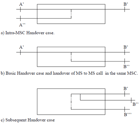
- Switch and Handover Device MSC-A. For all calls, except for ongoing voice group calls (see TS 43.068 for a definition) this unit is responsible for connecting the new path into the network via interface B'. In the case of ongoing voice group calls this unit is responsible for maintaining the connection between the down link group call channels and the active uplink. In specific cases it may be unnecessary to take any explicit action in the MSC concerning the handover device. The handover device interconnections are illustrated in Figure 2.
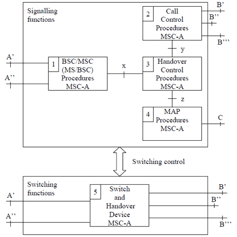
Figure 1: Functional composition of the controlling MSC (MSC-A) for supporting handover
(⇒ copy of original 3GPP image)
(⇒ copy of original 3GPP image)
For MS to MS calls in the same MSC the configuration in Figure 2 b applies. In this case interface B'' is internal to MSC-A and does not connect to another MSC.
The handover device can either be a three-party bridge or a switching facility without three-party connection capabilities. For a three-party bridge configuration the states of the handover device are as shown in Table 1. The three party configuration exists in the intermediate state. This type of handover device may reduce the interruption time. However, this may require noise reduction if one of the radio channels is unterminated at some time in the intermediate state.
For a handover device consisting of a simple switch there will be no intermediate state.
| Case | Initial Connection | Intermediate Connection | Resulting Connection | |
|---|---|---|---|---|
| Successful Procedure | Unsuccessful Procedure | |||
| Figure 2 a) | B' to A' | B' to A' and A'' | B' to A'' | B' to A' |
| Figure 2 b) | B' to A' | B' to A' and B'' | B' to B'' | B' to A' |
| Figure 2 c) | B' to B'' | B' to B''and B''' | B' to B''' | B' to B'' |
4.2 MSC-B p. 16
4.2.1 Role of MSC-B p. 16
In the Intra-MSC-B handover cases (including "BSS Internal Handover with MSC Support" with AoIP), the MSC-B keeps the control of the whole Intra-MSC-B handover procedure.
MSC-B notifies MSC-A or 3G_MSC-A of a successful Intra-MSC-B handover completion by using the A-HANDOVER-PERFORMED message.
If AoIP is supported by MSC-B and BSS, then the BSS or the MSC-B may initiate a "BSS Internal Handover with MSC Support" as described in detail in subclause 6.3.
The role of MSC-B is also to provide transcoder resources, if AoIP is supported and no transcoder is inserted in the BSS.
In the Inter-MSC handover case, the role of MSC-B (MSC-B') is only to provide radio resources control within its area. This means that MSC-B keeps control of the radio resources connection and release towards BSS-B. MSC-B will do some processing on the BSSMAP information received on the E-interface or A-interface whereas it will relay the DTAP information transparently between A interface and E-interface. MSC-A initiates and drives a subset of BSSMAP procedures towards MSC-B, while MSC-B controls them towards its BSSs to the extent that MSC-B is responsible for the connections of its BSSs. The release of the dedicated resources between MSC-B and BSS-B is under the responsibility of MSC-B and BSS B, and is not directly controlled by MSC-A. When clearing is to be performed due to information received from BSS-B, MSC-B shall transfer this clearing indication to MSC-A, to clear its connection with BSS-B, to terminate the dialogue with MSC-A through the E interface, and to release its circuit connection with MSC-A, if any. In the same way, the release of the connection to its BSS-B, is initiated by MSC-B, when the dialogue with MSC-A ends normally and a release is received from the circuit connection with MSC-A, if any, or when the dialogue with the MSC-A ends abnormally.
When a release is received by MSC-B for the circuit connection with MSC-A then MSC-B shall release the circuit connection.
In the Inter-system Inter-MSC handover case, the role of MSC-B (MSC-B') is only to provide radio resources control within its area. This means that MSC-B keeps control of the radio resources connection and release towards BSS-B. MSC-B will do some processing on the BSSMAP information received on the E-interface or A-interface whereas it will relay the DTAP information transparently between A interface and E-interface. 3G_MSC-A initiates and drives a subset of BSSMAP procedures towards MSC-B, while MSC-B controls them towards its BSSs to the extent that MSC-B is responsible for the connections of its BSSs. The release of the dedicated resources between MSC-B and BSS-B is under the responsibility of MSC-B and BSS B, and is not directly controlled by 3G_MSC-A. When clearing is to be performed due to information received from BSS-B, MSC-B shall transfer this clearing indication to 3G_MSC-A, to clear its connection with BSS-B, to terminate the dialogue with 3G_MSC-A through the E interface, and to release its circuit connection with 3G_MSC-A, if any. In the same way, the release of the connection to its BSS-B, is initiated by MSC-B, when the dialogue with 3G_MSC-A ends normally and a release is received from the circuit connection with MSC-A, if any, or when the dialogue with the MSC-A ends abnormally.
When a release is received by MSC-B for the circuit connection with 3G_MSC-A then MSC-B shall release the circuit connection.
For subsequent inter-MSC handover to an area where "Intra Domain Connection of RAN Nodes to Multiple CN Nodes" is applied, MSC-B can have multiple target CN nodes for each handover target in a pool-area as specified in TS 23.236.
MSC-B may support subsequent inter-MSC inter-system handover to a CSG cell. If MSC-B supports handover to a CSG cell, the serving BSS is served by MSC-B and provides a CSG ID for the target cell, and the call is not an emergency call, then MSC-B checks the CSG membership of the UE for the target cell using the CSG subscription data provided by the anchor MSC-A or 3G_MSC-A during the basic inter-MSC handover before proceeding with the subsequent handover procedure. If there is no subscription data for this CSG ID or the CSG subscription for the CSG ID has expired, MSC-B considers the membership check as failed.
For subsequent handover of an emergency call to a CSG cell, MSC-B shall skip the CSG membership check and proceed with the handover procedure.
For subsequent inter-PLMN handover to a CSG cell, if the anchor MSC-A or 3G_MSC-A provided a CSG ID list for the target PLMN during the basic inter-MSC handover, MSC-B shall validate the CSG membership of the UE in the target CSG cell using the CSG ID list for the target PLMN.
If the anchor MSC-A or 3G_MSC-A provided only a CSG ID list for the PLMN of MSC-B, then based on operator's configuration the MSC-B may allow the handover by validating the CSG membership of the UE in the target CSG cell using this CSG ID list. Otherwise, MSC-B shall reject the handover due to no CSG subscription information of the target PLMN-ID available.
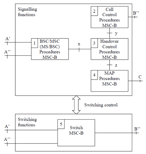
4.2.2 Functional composition of MSC-B and its interfaces for handover p. 17
The functional composition of an MSC acting as MSC-B is essentially the same as that of MSC-A. However, there are some differences. The functional units are as follows (see Figure 3).
Signalling functions:
- BSC/MSC (MS/BSC) Procedures MSC-B. This unit is used to control the signalling between the MSC, BSC and MS. Interface A'' is the connection to the new BSC, when an Intra-MSC handover takes place. Interface x represents the interworking connection to the Handover Control Procedures MSC-B.
- Call Control Procedures MSC-B. This unit is used for normal call control and signalling to MSC-A, or 3G_MSC-A in the case of inter-system inter-MSC handover.
- Handover Control Procedures MSC-B. This unit provides both the overall control of the handover procedure and interworking between the internal interfaces (x, y and z) in MSC-B.
- MAP Procedures MSC-B. This unit is responsible for controlling the exchange of MAP messages between MSC-A, or 3G_MSC-A, and MSC-B and for signalling to the VLR in MSC-B.
- Switch MSC-B. For all calls, except ongoing voice group calls (see TS 43.068 for a definition) this unit is responsible, with BSS-B, for connecting the circuit from MSC-A, or 3G_MSC-A, to BSS-B. This unit may also need to act as a handover device for Intra-MSC handovers controlled by MSC-B. In the case of ongoing voice group calls this unit is responsible for maintaining the connection between the group member currently assigned the uplink and the distribution device. In specific cases it may be unnecessary to take any explicit action in the MSC concerning the handover device.
![]()
![]()
![]()