Content for TR 22.858 Word version: 18.2.0
5.10 Use case: seamless path switch from a UE-to-UE direct communication to an indirect communication via an evolved residential gateway
5.11 Use case: seamless switching from a service hosting environment to an application server via an evolved residential gateway
5.12 Use case: local control of connectivity of UEs in a CPN
5.13 Use case on IP Traffic offload
5.14 Use case on PRAS sharing
...
...
5.10 Use case: seamless path switch from a UE-to-UE direct communication to an indirect communication via an evolved residential gateway p. 23
5.10.1 Description p. 23
This use case is depicted in Figure 5.10.1-1. It shows the scenario where two UEs have been in direct communication via a first path (Path #1) using 3GPP technology, but as the two UEs move apart from each other, they have to switch seamlessly to an indirect communication via one of the paths (Path #2, or Path #3) using 3GPP technology.
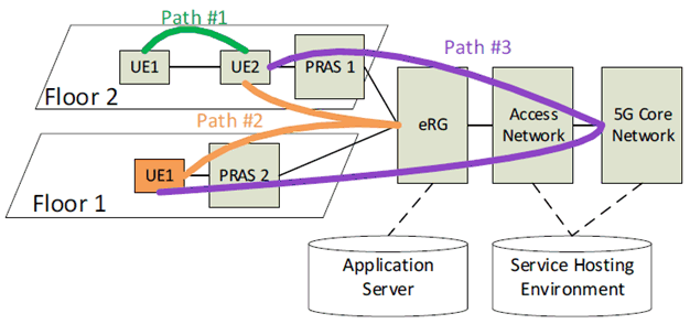
Figure 5.10.1-1: Seamless switching from a direct UE-to-UE path to an indirect path going through an evolved residential gateway.
(⇒ copy of original 3GPP image)
(⇒ copy of original 3GPP image)
5.10.2 Pre-conditions p. 23
Multiple Premises Radio Access Stations (PRASs) are deployed in the home (building) for serving different floors or rooms and interconnected via the eRG. The eRG is connected to the 5G-CN and the PRASs are connected to the 5G-CN via the eRG. UEs that are connected to PRASs can enjoy services offered by a Service Hosting Environment in the 3GPP network, and/or an Application Server (AS) via the eRG.
5.10.3 Service Flows p. 23
We consider a scenario where two UEs, UE1 and UE2, are connected via a 3GPP direct communication path (Path #1 in this example). Both UEs are assumed to be in proximity of one another (e.g. on the same floor) while enjoying their service via the direct link. An event occurs that triggers the move of UE1 away from UE2. While the UE1 moves away from UE2, it is the expectation of both UEs to continue their service seamlessly with the same QoS albeit through an indirect communication path via the network. Below we present the service flows:
- UE1 (e.g. smartphone or tablet) and UE2 (e.g. laptop) are both on the same floor (Floor 2 in this example) in the home and connected to each other via 3GPP direct communication path (Path #1 in this example). UE1 is receiving a direct service from UE2. This service has a specific QoS (e.g. latency sensitive).
- UE1 moves to another floor (Floor 1 in this example) whilst maintaining its service with UE2 with the same specific QoS.
- As the direct communication path (Path #1) between UE1 and UE2 degrades because the two UEs move apart, UE1 connects automatically to PRAS 2 while UE2 connects automatically to PRAS 1.
- The UE1-UE2 service is maintained with the same QoS through the indirect communication path (Path #2 in this example).
5.10.4 Post-conditions p. 24
The UE1-UE2 service is continued through indirect communication path going via the evolved residential gateway with the same QoS as through the original direct communication path.
5.10.5 Existing features partly or fully covering the use case functionality p. 24
Clause 6.2.3 of TS 22.261 Service continuity: Requirements
The 5G system shall support service continuity for a remote UE, when the remote UE changes from a direct network connection to an indirect network connection and vice-versa.
Clause 6.7.2 of TS 22.261: Priority, QoS, and policy control: Requirements
The 5G system shall be able to support E2E (e.g. UE to UE) QoS for a service.
The 5G system shall be able to support QoS for applications in a Service Hosting Environment.
Clause 7.6.1 of TS 22.261 AR/VR: Gaming and Training Data Exchanging
This use case is characterized by the exchange of the gaming or training service data between two 5G AR/VR devices.
Clause 7A.1 of TS 22.278: includes requirements on managing the switch from a direct communication path to an indirect communication path. These requirements are addressed in TS 23.287.
Clause 6.23.2 of TS 22.261 includes requirements for QoS Monitoring which are addressed in clause 5.33.3 of TS 23.501 QoS Monitoring to Assist URLLC Service.
5.10.6 Potential New Requirements needed to support the use case p. 24
[PR 5.10.6-001]
The 5G system shall be able to minimize disruption to the user when a UE switches from a direct communication path between the UEs to an indirect communication path going through the eRG and there is connectivity to the 5G system.
[PR 5.10.6-002]
The 5G system shall support real time E2E QoS monitoring and control for any data traffic path (i.e. from/to a UE to/from the 5GC and to/from another UE) via a PRAS and an eRG when there is connectivity to the 5G system.
5.11 Use case: seamless switching from a service hosting environment to an application server via an evolved residential gateway p. 25
5.11.1 Description p. 25
This use case describes a scenario of service continuity for a UE consuming a low latency service provided by a service hosting environment. The low latency service (e.g. gaming) is maintained with the same QoS settings as the UE moves from the service hosting environment to an Application Server (AS) connected to an evolved Residential Gateway (eRG). While the AS can be a standalone platform, it can also be an on-site extension of an in-network Service Hosting Environment, e.g. an edge computing platform. In this case, the operator of the AS (e.g., a MEC server operator), can influence discovering/authorizing/orchestrating a residential application/service on the AS. The AS can be under the control of a 5G network operator, a customer or a third party. The service hosting environment and AS are served by the same 3GPP 5G core network (5G-CN).
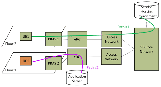
Figure 5.11.1-1: Seamless switching to an Application Server via an evolved residential gateway.
(⇒ copy of original 3GPP image)
(⇒ copy of original 3GPP image)
5.11.2 Pre-conditions p. 25
A service hosting environment is attached to the 3GPP 5G-CN. An AS connects to the same 3GPP 5G-CN via an eRG. An indoor base station is deployed in the residential environment and is connected to the 3GPP 5G-CN via the eRG. The AS can be either in the MNO domain (i.e. a trusted application) or external to the MNO domain (i.e. an authorized third-party application).
5.11.3 Service Flows p. 25
We consider a scenario where a given UE, UE1, is receiving a service from a service hosting environment via a Premises Radio Access Station (PRAS 1) connected to the 3GPP 5G-CN. While the UE is enjoying its service, an event occurs that triggers the move of UE1 to an AS (e.g. UE1 arrives home). This AS is connected to the same 5G-CN via an eRG. As this event occurs, it is the expectation of UE1 to continue its service seamlessly with the same QoS albeit through the eRG in the AS. Below we present the service flows:
- UE consumes a low latency service (e.g. gaming) provided by a service hosting environment through the 3GPP 5G-CN (Path #1). This low latency service has a specific QoS.
- UE moves to an AS connected to the same 5G-CN via an eRG. The UE connects automatically to the PRAS 2 which in turn is connected to the eRG.
- The UE continues to receive its service seamlessly and with the same QoS through the eRG in the AS.
5.11.4 Post-conditions p. 26
The UE service is continued seamlessly through the eRG in the AS and with the same QoS as it was in the service hosting environment. For the purpose of demonstrating the path switch, Path #2 in Figure 5.11.1-1 is an example the 5G System can choose to ensure seamless switching.
5.11.5 Existing features partly or fully covering the use case functionality p. 26
Clause 6.5.2 of TS 22.261 Efficient user plane: Requirements
Based on operator policy, application needs, or both, the 5G system shall support an efficient user plane path, modifying the path as needed when the UE moves or application changes location, between a UE in an active communication and:
- an application in a Service Hosting Environment; or
- an application server located outside the operator's network.
- another location served by a different Service Hosting Environment; or
- another location served by an application server located outside the operator's network, and vice versa.
- within a Service Hosting Environment; or
- from a Service Hosting Environment to another Service Hosting Environment; or
- from a Service Hosting Environment to an application server located place outside the operator's network, and vice versa.
5.11.6 Potential New Requirements needed to support the use case p. 26
[PR 5.11.6-001]
The 5G system shall be able to provide support for an eRG to interconnect with an Application Server.
[PR 5.11.6-002]
The 5G system shall be able to maintain QoS for a UE, when it is moving between a Service Hosting Environment and an Application Server in the CPN that is connected to an eRG.
5.12 Use case: local control of connectivity of UEs in a CPN p. 27
5.12.1 Description p. 27
In many residential scenarios, indoor coverage will require deployment of multiple PRASs or WLAN Access Points (APs). It is expected that both 3GPP RATs and non-3GPP RATs (e.g. WLAN) offer wireless connectivity allowing UEs to connect to local or external IP networks via the eRG, thus, as users move through the home, switching of connectivity between different PRASs or APs is required to maintain service quality.
For certain services requiring low latency and high throughput such as playing an interactive game on a VR/AR headset UE, there is a need to connect to a dedicated device within the CPN, for example a gaming console or a set-top-box.
The gaming console will provide the necessary service experience such as reactiveness when computing and rendering a new AR/VR scene displayed on the VR/AR headset (UE #1). In this use case, the gaming console can either be a 3GPP device, a non-3GPP device or support both RATs (3GPP and non-3GPP). The gaming console is part of the CPN.
The VR/AR headset (UE #1) will connect to the gaming console via one of the points of access (PRAS or AP) connected to the eRG.
To guarantee the required bandwidth and latency to the participants in the game, an authorized user e.g. the homeowner (Authorised Administrator) can initially, or dynamically via e.g. the gaming console or the eRG, reserve temporary access or capacity to particular UEs accessing particular PRASs and APs in the CPN during the game. Other UEs that generally are provided access to these PRASs and APs in the CPN, will during the game have a restricted or no access to certain PRASs and APs.
As a player moves around in the home, there will be a need to handover the VR/AR headset (UE #1) connection from one PRAS or AP to another. Although the VR/AR headset (UE #1) can connect simultaneously to an AP and to a PRAS, the VR/AR headset (UE #1) is not able to take educated decisions on its own with regards to capabilities of alternative accesses in the home, e.g. if a candidate handover access is overloaded. However, a centralized application can distribute accesses with respect to relevant applicative parameters like VR/AR headset, the position and the direction of the UE and buffer level. Besides, the centralized application can know the building map and where (e.g. location) the different players are and where they can be expected to move as the game progress.
The game application can also know the overall context for all players and can compute the best path for each UE for connecting to a particular point of access (PRAS or AP). This application can predict and adapt access to each 3GPP RAT or non-3GPP RAT for providing the best global service experience applied to each individual player at each time. The application can also learn from individual service experience resulting from past decisions applied to input parameters to improve access decisions.
To optimise the gaming experience, the gaming console can control which particular VR/AR headset (UE #1 or UE #2) connects to a particular point of access (PRAS #1 or PRAS #2 or AP #1 or AP #2) to reach the application. For example, the gaming console can disable a VR/AR headset (UE #1) to connect PRAS (PRAS #2) in order to force this VR/AR headset (UE #1) to connect to PRAS (PRAS #1).
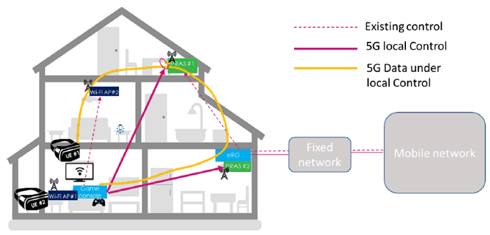
Figure 5.12.1-1: Local control of PRASs for UE #1 to access CPN device
(⇒ copy of original 3GPP image)
(⇒ copy of original 3GPP image)
5.12.2 Pre-conditions p. 28
John and his game player friend Paul wear a 5G-enabled VR/AR headset (UE #1, UE #2). They love to play their favourite immersive game taking place throughout the whole house. The following pre-conditions and assumptions apply to this use case.
- John, as the authorized user, has appropriately configured the devices in his house for the game.
- Multiple PRASs (PRAS #1, PRAS #2) (3GPP RAT) are deployed in John's home, connected to the eRG.The home is equipped with several WLAN APs (AP #1, AP #2) (non-3GPP RAT), connected to the eRG.
- Game players use VR/AR headsets (UE #1, UE #2) that require low latency and high throughput.
- There is a gaming console in the home providing the expected gaming service experience such as reactiveness when computing and rendering a new AR/VR scene to be display on a VR/AR headset (UE #1, UE #2).
- Game players VR/AR headsets (UE #1, UE #2) can communicate with the gaming console over either of the 3GPP or non-3GPP RATs and the eRG.
- The gaming console contains a map of the house.
- The game play application knows the user locations.
5.12.3 Service Flows p. 28
The service flow for this use case is as follows:
- John reserves temporary access or capacity for the relevant devices for the duration of the game;
- John launches the multi-player augmented reality game from the residential gaming console indicating multi-RAT connectivity;
- the gaming console communicates with the PRASs and APs to allow to control of the connectivity from the small base station to the gaming console;
- John and Paul start playing the game from the living-room and power their VR/AR headset (UE #1 and UE #2);
- each VR/AR headset (UE #1, UE #2) initially connects the gaming console from a suitable PRAS or AP;
- the gaming console updates the game play each time a player moves indoor and forces the AR/VR headset (UE #1, UE #2) to connect to a particular point of access (PRAS #1 or PRAS #2 or AP #1 or AP #2); and
- when Paul moves, the gaming console communicates with the PRASs (enable UE #1 on PRAS #1, disable UE #1 on PRAS #2) to force the VR/AR headset (UE #1) to connect to PRAS #1 to reach the gaming console.
5.12.4 Post-conditions p. 29
John and his friends can move throughout the home, from room to room on all floors, experiencing no latency when their VR/AR headset displays an augmented reality scene.
5.12.5 Existing features partly or fully covering the use case functionality p. 29
Clause 6.3.2.1 of TS 22.261: The 5G system shall be able to support mobility between the supported access networks (e.g. NG-RAN, WLAN, fixed broadband access network, 5G satellite access network).
Clause 6.3.2.4 of TS 22.261: The 5G system shall support use of a home base station that supports multiple access types (e.g. 5G RAT, WLAN access, fixed broadband access).
Clause 6.7.2 of TS 22.261: A 5G system with multiple access technologies shall be able to select the combination of access technologies to serve a UE on the basis of the targeted priority, pre-emption, QoS parameters and access technology availability.
Clause 5.5.3 of TS 22.220: It shall be possible to support service continuity, including handover, between a H(e)NB cell and other cells and between H(e)NB cells. This includes H(e)NB cells in residential and enterprise environment.
Clause 5.7.2 of TS 22.220: A H(e)NB subsystem shall be able to support Local IP Access in order to provide access for IP capable UEs connected via a H(e)NB subsystem (i.e. using H(e)NB radio access) to other IP capable entities in the same residential/enterprise IP network.
5.12.6 Potential New Requirements needed to support the use case p. 29
[PR. 5.12.6-001]
The 5G system shall provide means to enable/disable a UE to connect to a Customer Premises Network device via a particular Premises Radio Access Station.
[PR. 5.12.6-002]
The 5G system shall provide means for an authorized user to prioritize access for a certain UE in a PRAS and CPN, within the limits given by the operator policy.
[PR. 5.12.6-003]
The 5G system shall minimize service disruption when a CPN communication path changes between two PRASes.
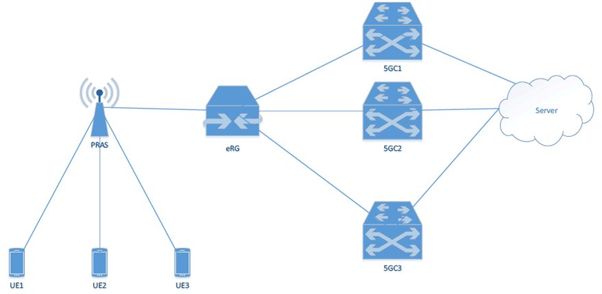
5.13 Use case on IP Traffic offload p. 29
5.13.1 Description p. 29
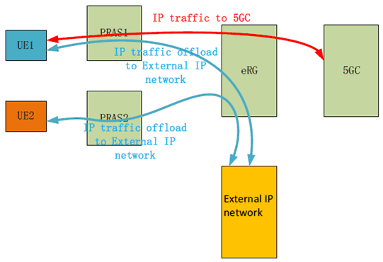
This use case assumes that one or more Premises Radio Access Stations (PRASs) were deployed in home. The IP traffic via the PRAS can be offloaded towards an external IP network at eRG directly, without going through 5GC, which is depicted in Figure 5.13.1-1. The external IP network can be enterprise private network, or internet.
5.13.2 Pre-Conditions p. 30
The following pre-conditions and assumptions apply to this use case:
- One or more PRAS were deployed in a residential home.
- The PRAS provides cellular access to UEs.
- The PRAS is connected to an eRG via wireline or wireless link.
- The eRG can support an external IP connectivity.
5.13.3 Service Flows p. 30
Jim installed a PRAS in his house to improve the quality of experience.
Some friends will come to Jim's house and play online games with extremely low latency together. Jim's game experience perhaps declined due to the excessive core network pressure.
The specific IP traffic can be offloaded to the external IP network automatically at eRG when the QoS is detected not meet the requirement in PRAS or eRG.
Jim can configure which types of service are prioritized to be offloaded in the systematic backstage of PRAS or eRG, and the systematic back-stage provides an approach to configure the PRAS or eRG.
5.13.4 Post-Conditions p. 30
Jim and his friend can enjoy the online game in a forever good user experience.
5.13.5 Existing features partly or fully covering the use case functionality p. 30
3GPP TS 22.101 "Service principles" specifies the requirements for Selected IP Traffic Offload (SIPTO) for PS Domain only.
3GPP TS 22.220 "Service requirements for Home Node B (HNB) and Home eNode B (HeNB)" specifies the requirements for Selected IP Traffic Offload (SIPTO) at Local Network.
3GPP TS 23.501 "System architecture for the 5G System (5GS) stage 2" specifies the concept of "UL CL" (Uplink classifier) and BP (Branching Point). UL CL is a functionality supported by an UPF that aims at diverting (locally) some traffic matching traffic filters provided by the SMF, and BP provides forwarding of UL traffic towards the different PDU Session Anchors and merge of DL traffic to the UE i.e. merging the traffic from the different PDU Session Anchors on the link towards the UE.
5.13.6 Potential New Requirements needed to support the use case p. 31
[PR. 5.13.6-001]
The 5G system shall be able to support IP traffic offload in CPN.
5.14 Use case on PRAS sharing p. 31
5.14.1 Description p. 31
This use case assumes that one or more Premises Radio Access Stations (PRASs) were already deployed in home. The mobile phones of family members or the visitors, which have different subscriptions to operators, need access to the 5GC via the deployed PRAS(s).
5.14.2 Pre-Conditions p. 31
The following pre-conditions and assumptions apply to this use case:
- One or more PRAS were deployed in a residential home.
- The PRAS provides cellular access to UEs.
- The PRAS is connected to an eRG via wireline or wireless link.
- The mobile phones of family members or the visitor have individual subscriptions to the 5G system, and these subscriptions may be different operators.
5.14.3 Service Flows p. 31
Jim's smart phone is connecting to the PRAS and Jim can enjoy the internet service via MNO1's core network.
Alice has no roaming subscription with MNO1, so she only accesses the internet service via MNO2's core network.
Jim can enter the systematic backstage of PRAS to manage the MNOs that policy allowed access. He adds the MNO2 to the PRAS system, and the provisioning for PRAS and eRG can be completed automatically.
5.14.4 Post-Conditions p. 32
Alice could enjoy the internet service on her mobile phone via PRAS with MNO2's core network.
5.14.5 Existing features partly or fully covering the use case functionality p. 32
3GPP TS 22.101 "Service principles" specifies the requirements for RAN sharing enhancements.
5.14.6 Potential New Requirements needed to support the use case p. 32
[PR. 5.14.6-001]
The 5G system shall be able to support PRAS sharing between multiple PLMNs.
![]()
![]()
![]()