Content for TS 38.331 Word version: 18.0.0
1…
4…
5…
5.2.2.4…
5.3…
5.3.3…
5.3.5…
5.3.5.5…
5.3.5.6…
5.3.5.7…
5.3.5.13…
5.3.5.17…
5.3.6…
5.3.8…
5.3.13…
5.3.14…
5.4…
5.5…
5.5.3…
5.5.4…
5.5.4.15…
5.5.4.23…
5.5.5…
5.5a…
5.7…
5.7.4…
5.7.8…
5.7.12…
5.8…
5.8.9…
5.8.9.2…
5.8.9.8…
5.8.10…
5.8.11…
5.9…
5.10…
6…
6.2.2…
6-2-2-23…
6-2-2-27…
6-2-2-43…
6-2-2-47…
6.3…
6.3.2…
6-3-2-27…
6-3-2-49…
6-3-2-73…
6-3-2-95…
6-3-2-108…
6-3-2-134…
6-3-2-162…
6-3-2-188…
6-3-2-213…
6-3-2-243…
6-3-2-271…
6-3-2-297…
6-3-2-341…
6.3.3…
6-3-3-25…
6-3-3-51…
6.3.4…
6.3.5…
6-3-5-25…
6.3.6…
6.4…
7…
9…
11…
A…
A.4…
B…
4 General
4.1 Introduction
4.2 Architecture
4.2.1 UE states and state transitions including inter RAT
4.2.2 Signalling radio bearers
4.3 Services
4.3.1 Services provided to upper layers
4.3.2 Services expected from lower layers
4.4 Functions
...
...
4 General p. 36
4.1 Introduction p. 36
This specification is organised as follows:
- clause 4.2 describes the RRC protocol model;
- clause 4.3 specifies the services provided to upper layers as well as the services expected from lower layers;
- clause 4.4 lists the RRC functions;
- clause 5 specifies RRC procedures, including UE state transitions;
- clause 6 specifies the RRC messages in ASN.1 and description;
- clause 7 specifies the variables (including protocol timers and constants) and counters to be used by the UE;
- clause 8 specifies the encoding of the RRC messages;
- clause 9 specifies the specified and default radio configurations;
- clause 10 specifies generic error handling;
- clause 11 specifies the RRC messages transferred across network nodes;
- clause 12 specifies the UE capability related constraints and performance requirements.
4.2 Architecture p. 36
4.2.1 UE states and state transitions including inter RAT p. 36
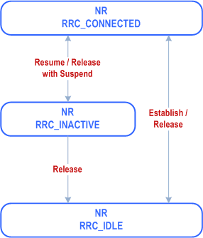
A UE is either in RRC_CONNECTED state or in RRC_INACTIVE state when an RRC connection has been established. If this is not the case, i.e. no RRC connection is established, the UE is in RRC_IDLE state. The RRC states can further be characterised as follows:
-
RRC_IDLE:
- A UE specific DRX may be configured by upper layers;
- At lower layers, the UE may be configured with a DRX for PTM transmission of MBS broadcast;
- UE controlled mobility based on network configuration;
-
The UE:
- Monitors Short Messages transmitted with P-RNTI over DCI (see clause 6.5);
- Monitors a Paging channel for CN paging using 5G-S-TMSI, except if the UE is acting as a L2 U2N Remote UE;
- If configured by upper layers for MBS multicast reception, while SDT procedure is not ongoing, monitors a Paging channel for paging using TMGI;
- Performs neighbouring cell measurements and cell (re-)selection;
- Acquires system information and can send SI request (if configured);
- Performs logging of available measurements together with location and time for logged measurement configured UEs;
- Performs idle/inactive measurements for idle/inactive measurement configured UEs;
- If configured by upper layers for MBS broadcast reception, acquires MCCH change notification and MBS broadcast control information and data.
-
RRC_INACTIVE:
- A UE specific DRX may be configured by upper layers or by RRC layer;
- At lower layers, the UE may be configured with a DRX for PTM transmission of MBS broadcast and/or a DRX for PTM transmission of MBS multicast;
- UE controlled mobility based on network configuration;
- The UE stores the UE Inactive AS context;
- A RAN-based notification area is configured by RRC layer;
- Transfer of unicast data and/or signalling to/from UE over radio bearers configured for SDT.
-
The UE:
- Monitors Short Messages transmitted with P-RNTI over DCI (see clause 6.5);
- While T319a is running, monitors control channels associated with the shared data channel to determine if data is scheduled for it;
- While T319a is not running, monitors a Paging channel for CN paging using 5G-S-TMSI and RAN paging using fullI-RNTI, except if the UE is acting as a L2 U2N Remote UE;
- If configured by upper layers for MBS multicast reception, while T319a is not running, monitors a Paging channel for paging using TMGI;
- Performs neighbouring cell measurements and cell (re-)selection;
- Performs RAN-based notification area updates periodically and when moving outside the configured RAN-based notification area;
- Acquires system information and, while SDT procedure is not ongoing, can send SI request (if configured);
- While SDT procedure is not ongoing, performs logging of available measurements together with location and time for logged measurement configured UEs;
- While SDT procedure is not ongoing, performs idle/inactive measurements for idle/inactive measurement configured UEs;
- If configured by upper layers for MBS broadcast reception, acquires MCCH change notification and MBS broadcast control information and data;
- If configured for MBS multicast reception in RRC_INACTIVE, acquires multicast MCCH change notification and MBS multicast control information and data;
- Transmits SRS for Positioning.
-
RRC_CONNECTED:
- The UE stores the AS context;
- Transfer of unicast data to/from UE;
- Transfer of MBS multicast data to UE;
- At lower layers, the UE may be configured with a UE specific DRX;
- At lower layers, the UE may be configured with a DRX for PTM transmission of MBS broadcast and/or a DRX for MBS multicast;
- At lower layers, the UE may be configured with a cell specific cell DTX/DRX;
- For UEs supporting CA, use of one or more SCells, aggregated with the SpCell, for increased bandwidth;
- For UEs supporting DC, use of one SCG, aggregated with the MCG, for increased bandwidth;
- Network controlled mobility within NR, to/from E-UTRA, and to UTRA-FDD;
- Network controlled mobility (path switch) between a serving cell and a L2 U2N Relay UE, or vice versa.
-
The UE:
- Monitors Short Messages transmitted with P-RNTI over DCI (see clause 6.5), if configured;
- Monitors control channels associated with the shared data channel to determine if data is scheduled for it;
- Provides channel quality and feedback information;
- Performs neighbouring cell measurements and measurement reporting;
- Acquires system information;
- Performs immediate MDT measurement together with available location reporting;
- If configured by upper layers for MBS broadcast reception, acquires MCCH change notification and MBS broadcast control information and data.

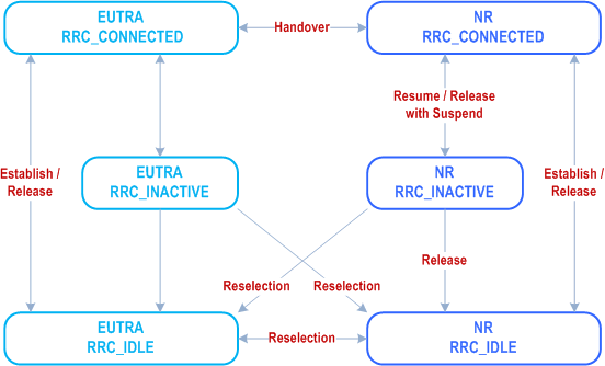
Figure 4.2.1-2 illustrates an overview of UE state machine and state transitions in NR as well as the mobility procedures supported between NR/5GC, E-UTRA/EPC and E-UTRA/5GC.

Figure 4.2.1-3 illustrates the mobility procedure supported between NR/5GC and UTRA-FDD.

4.2.2 Signalling radio bearers p. 39
"Signalling Radio Bearers" (SRBs) are defined as Radio Bearers (RBs) that are used only for the transmission of RRC and NAS messages. More specifically, the following SRBs are defined:
- SRB0 is for RRC messages using the CCCH logical channel;
- SRB1 is for RRC messages (which may include a piggybacked NAS message) as well as for NAS messages prior to the establishment of SRB2, all using DCCH logical channel;
- SRB2 is for NAS messages and for RRC messages which include logged measurement information, all using DCCH logical channel. SRB2 has a lower priority than SRB1 and may be configured by the network after AS security activation;
- SRB3 is for specific RRC messages when UE is in (NG)EN-DC or NR-DC, all using DCCH logical channel;
- SRB4 is for RRC messages which include application layer measurement report information, all using DCCH logical channel. SRB4 has a lower priority than SRB1 and can only be configured by the network after AS security activation.
- SRB5 is for RRC messages which include application layer measurement report information, all using DCCH logical channel. SRB5 has a lower priority than SRB1 and SRB3 and can only be configured by the SN serving the SCG when the UE is in NR-DC, after AS security activation.
4.3 Services p. 40
4.3.1 Services provided to upper layers p. 40
The RRC protocol offers the following services to upper layers:
- Broadcast of common control information;
- Notification of UEs in RRC_IDLE, e.g. about a mobile terminating call;
- Notification of UEs about ETWS and/or CMAS;
- Transfer of dedicated signalling;
- Broadcast of positioning assistance data;
- Transfer of application layer measurement configuration and reporting.
4.3.2 Services expected from lower layers p. 40
In brief, the following are the main services that RRC expects from lower layers:
- Integrity protection, ciphering and loss-less in-sequence delivery of information without duplication;
4.4 Functions p. 40
The RRC protocol includes the following main functions:
-
Broadcast of system information:
- Including NAS common information;
- Information applicable for UEs in RRC_IDLE and RRC_INACTIVE (e.g. cell (re-)selection parameters, neighbouring cell information) and information (also) applicable for UEs in RRC_CONNECTED (e.g. common channel configuration information);
- Including ETWS notification, CMAS notification;
- Including positioning assistance data.
-
RRC connection control:
- Paging;
- Establishment/ modification/ suspension/ resumption/ release of RRC connection, including e.g. assignment/ modification of UE identity (C-RNTI, fullI-RNTI, etc.), establishment/ modification/ suspension/ resumption/ release of SRBs (except for SRB0);
- Access barring;
- Initial AS security activation, i.e. initial configuration of AS integrity protection (SRBs, DRBs) and AS ciphering (SRBs, DRBs);
- RRC connection mobility including e.g. intra-frequency and inter-frequency handover, path switch from a PCell to a target L2 U2N Relay UE or from a L2 U2N Relay UE to a target PCell or from a source L2 U2N Relay UE to a target L2 U2N Relay UE, associated AS security handling, i.e. key/algorithm change, specification of RRC context information transferred between network nodes;
- Establishment/ modification/ suspension/ resumption/ release of RBs carrying user data (DRBs/MRBs);
- Radio configuration control including e.g. assignment/ modification of ARQ configuration, HARQ configuration, DRX configuration;
- In case of DC, cell management including e.g. change of PSCell, addition/ modification/ release of SCG cell(s);
- In case of CA, cell management including e.g. addition/ modification/ release of SCell(s);
- In case of MP, path management including e.g. addition/ modification/ release of indirect path;
- QoS control including assignment/ modification of semi-persistent scheduling (SPS) configuration and configured grant configuration for DL and UL respectively, assignment/ modification of parameters for UL rate control in the UE, i.e. allocation of a priority and a prioritised bit rate (PBR) for each RB of UE and logical channel of IAB-MT.
- Recovery from radio link failure.
- Inter-RAT mobility including e.g. AS security activation, transfer of RRC context information;
-
Measurement configuration and reporting:
- Establishment/ modification/ release of measurement configuration (e.g. intra-frequency, inter-frequency and inter- RAT measurements);
- Setup and release of measurement gaps;
- Measurement reporting.
- Configuration of BAP entity and BH RLC channels for the support of IAB-node.
- Configuration of SRAP entity and Uu/PC5 Relay RLC channels for the support of L2 U2N relay.
- Other functions including e.g. generic protocol error handling, transfer of dedicated NAS information, transfer of UE radio access capability information.
- Support of self-configuration and self-optimisation.
- Support of measurement logging and reporting for network performance optimisation, as specified in TS 37.320;
- Support of transfer of application layer measurement configuration and reporting.
- Configuration of side control information for NCR-node.