Content for TR 26.928 Word version: 17.0.0
0…
4…
4.1.2…
4.2…
4.3…
4.4…
4.5…
4.6…
4.6.7
4.7…
4.9…
5…
6…
7…
8
A…
A.4…
A.7…
A.10…
A.13
A.14
A.15
A.16…
A.19…
A.22…
4.1.2 Degrees of Freedom and XR Spaces
4.1.3 Tracking and XR Viewer Pose Generation
4.1.4 XR Spatial Mapping and Localization
...
...
4.1.2 Degrees of Freedom and XR Spaces p. 13
A user acts in and interacts with extended realities as shown in Figure 4.1-2. Actions and interactions involve movements, gestures, body reactions. Thereby, the Degrees of Freedom (DoF) describe the number of independent parameters used to define movement of a viewport in the 3D space.
Any consistent interaction for an XR application with XR hardware is assumed to be restricted to an XR session. Once an XR session has been successfully established, it can be used to poll the viewer pose, query information about the user's environment, and present imagery to the user.
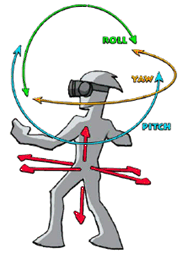
Figure 4.1-2: Different degrees of freedom for a user in extended realities
(⇒ copy of original 3GPP image)
(⇒ copy of original 3GPP image)
Typically, the following different types of Degrees-of-Freedom are described (and also shown in Figure 4.1-3).
- 3DoF: Three rotational and un-limited movements around the X, Y and Z axes (respectively pitch, yaw and roll). A typical use case is a user sitting in a chair looking at 3D 360 VR content on an HMD (see Figure 4.1-3 (a)).
- 3DoF+: 3DoF with additional limited translational movements (typically, head movements) along X, Y and Z axes. A typical use case is a user sitting in a chair looking at 3D 360 VR content on an HMD with the capability to slightly move his head up/down, left/right and forward/backward (see Figure 4.1-3 (b)).
- 6DoF: 3DoF with full translational movements along X, Y and Z axes. Beyond the 3DoF experience, it adds (i) moving up and down (elevating/heaving); (ii) moving left and right (strafing/swaying); and (iii) moving forward and backward (walking/surging). A typical use case is a user freely walking through 3D 360 VR content (physically or via dedicated user input means) displayed on an HMD (see Figure 4.1-3 (d)).
- Constrained 6DoF: 6DoF with constrained translational movements along X, Y and Z axes (typically, a couple of steps walking distance). A typical use case is a user freely walking through VR content (physically or via dedicated user input means) displayed on an HMD but within a constrained walking area (see Figure 4.1-3 (c)).
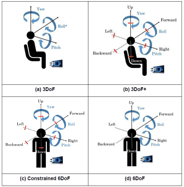
Another term for Constrained 6DoF is Room Scale VR being a design paradigm for XR experiences which allows users to freely walk around a play area, with their real-life motion reflected in the XR environment.
The Degrees of Freedom may also be used to describe the tracking capabilities of an XR device. For more details on tracking, refer to clauses 4.1.3 and 4.1.4. Content and tracking capabilities of a device do not necessarily have to match. However, the user is preferably informed by the application on any differences between content and tracking capabilities in terms of number/types of degrees of freedom. .
Spaces provide a relation of the user's physical environment with other tracked entities. An XR Space represents a virtual coordinate system with an origin that corresponds to a physical location. The world coordinate system is the coordinate system in which the virtual world is created. Coordinate systems are essential for operating in 3-dimensional virtual and real worlds for XR applications.
As an example, a coordinate system is defined by OpenXR [16] in clause 2.15 as well as for WebXR [17], both using a Cartesian right-handed coordinate system as shown in Figure 4.1-4. This coordinate system is right-handed in sense that, where +X is considered "Right", +Y is considered "Up", and -Z is considered "Forward".
A coordinate system is expected to be a rectangular Cartesian in which all axes are equally scaled.
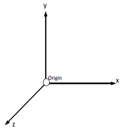
A three-dimensional vector is defined by the (x,y,z) coordinates. If used to represent physical distances (rather than e.g. velocity or angular velocity) and not otherwise specified, values are in meters. A position in the XR space is a 3D-vector representing a position within a space and relative to the origin.
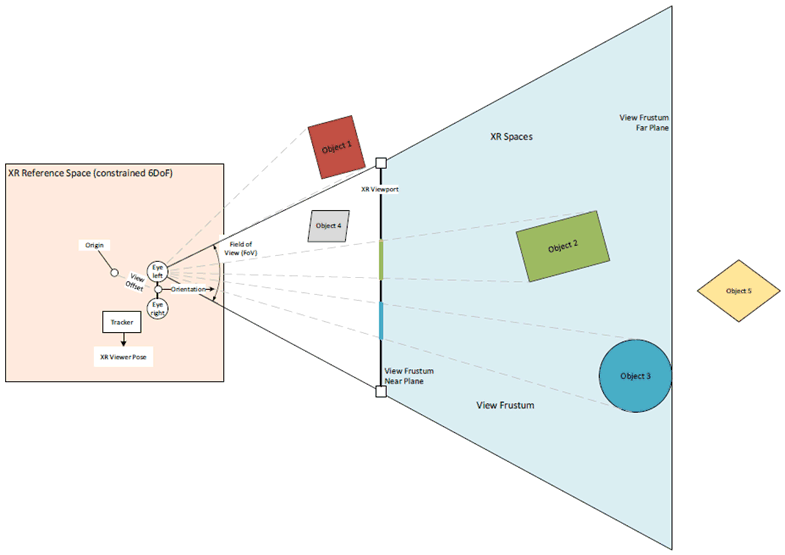
An XR reference space is one of several common XR Spaces that can be used to establish a spatial relationship with the user's physical environment. An XR reference space may be restricted, determining the ability by the user to move. This aligns with the definitions above as well as Figure 4.1-3, namely an XR reference space providing the degrees of freedom for a user.
- For 3DoF, the XR reference space is limited to a single position.
- For 3DoF+, the XR reference space is limited to a small space centered around a single position, a small bounding box, limited to positions attainable with head movements only, around a single position is provided.
- For constrained 6DoF, the XR reference space has a native bounds geometry describing the border around the space, which the user can expect to safely move within. Such borders may for example be described by polygonal boundary given as an array representing a loop of points at the edges of the safe space. The points describe offsets from the origin in meters.
- For 6DoF, the XR reference space is unlimited and basically includes the whole universe.
Unless the user does a reconfiguration, XR reference spaces within an XR session are static, i.e. the space the user can move in is restricted by the initial definition.
An XR View describes a single view into an XR scene for a given time. Each view corresponds to a display or portion of a display used by an XR device to present the portion of the scene to the user. Rendering of the content is expected to be done to well align with the view's physical output properties, including the field of view, eye offset, and other optical properties. A view, among others, has associated
- a view offset, describing a position and orientation of the view in the XR reference space,
- an eye describing which eye this view is expected to be shown. Displays may support stereoscopic or monoscopic viewing.
- The position in the XR space is a 3D-vector representing the position within a space and relative to the origin defined by the (x,y,z) coordinates. If used to represent physical distances, x, y, and z are in meters.
- The orientation in the XR space is a quaternion representing the orientation within a space and defined by a four-dimensional or homogeneous vector with (x,y,z,w) coordinates, with w being the real part of the quarternion and x, y and z the imaginary parts.
4.1.3 Tracking and XR Viewer Pose Generation p. 18
In XR applications, an essential element is the use of spatial tracking. Based on the tracking and the derived XR Viewer Pose, content is rendered to simulate a view of virtual content.
XR viewer poses and motions can be sensed by Positional Tracking, i.e. the process of tracing the XR scene coordinates of moving objects in real-time, such as HMDs or motion controller peripherals. Positional Tracking allows to derive the XR Viewer Pose, i.e. the combination of position and orientation of the viewer. Different types of tracking exist:
- Outside-In Tracking: a form of positional tracking and, generally, it is a method of optical tracking. Tracking sensors placed in a stationary location and oriented towards the tracked object that moves freely around a designated area defined by sensor coverage.
- Inside-out Tracking: a method of positional tracking commonly used in virtual reality (VR) technologies, specifically for tracking the position of head-mounted displays (HMDs) and motion controller accessories whereby the location of the cameras or other sensors that are used to determine the object's position in space are located on the device being tracked (e.g. HMD).
- World Tracking: a method to create AR experiences that allow a user to explore virtual content in the world around them with a device's back-facing camera using a device's orientation and position, and detecting real-world surfaces, as well as known images or objects.
- Simultaneous Localization and Mapping (SLAM) is the computational problem of constructing or updating a map of an unknown environment while simultaneously keeping track of the user's location within an unknown environment. For more details refer on SLAM, refer to clause 4.1.4.
4.1.4 XR Spatial Mapping and Localization p. 18
Spatial mapping, i.e. creating a map of the surrounding area, and localization, i.e. establishing the position of users and objects within that space, are some of the key areas of XR and in particular AR. Multiple sensor inputs are combined to get a better localization accuracy, e.g., monocular/stereo/depth cameras, radio beacons, GPS, inertial sensors, etc.
Some of the methods involved are listed below:
- Spatial anchors are used for establishing the position of a 3D object in a shared AR/MR experience, independent of the individual perspective of the users. Spatial anchors are accurate within a limited space (e.g. 3m radius for the Microsoft® Mixed Reality Toolkit). Multiple anchors may be used for larger spaces.
- Simultaneous Localization and Mapping (SLAM) is used for mapping previously unknown environments, while also maintaining the localization of the device/user within that environment.
- Visual Localization, e.g., vSLAM, Visual Positioning System (VPS), etc., perform localization using visual data from, e.g., a mobile camera, combined with other sensor data.
- Cloud services may be used for storing, retrieving and updating spatial data. For larger public spaces, crowdsourcing may be used to keep the data updated and available to all.
- A Spatial Computing Server that collects data from multiple sources and processes it to create spatial maps including, but not limited to, visual and inertial data streamed from XR devices. The service can then provide this information to other users and also assist in their localization based on the data received from them.
![]()
![]()
![]()