Content for TR 26.928 Word version: 17.0.0
0…
4…
4.1.2…
4.2…
4.3…
4.4…
4.5…
4.6…
4.6.7
4.7…
4.9…
5…
6…
7…
8
A…
A.4…
A.7…
A.10…
A.13
A.14
A.15
A.16…
A.19…
A.22…
4.4 XR Engines and Rendering
4.4.1 Introduction
4.4.2 Briefly on Rendering Pipelines
4.4.3 Real-time 3D Rendering
4.4.4 Network Rendering and Buffer Data
...
...
4.4 XR Engines and Rendering p. 28
4.4.1 Introduction p. 28
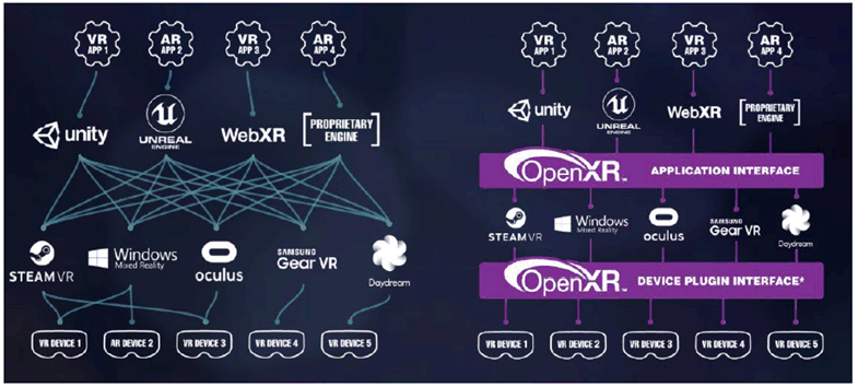
XR engines provide a middleware that abstracts hardware and software functionalities for developers of XR applications. In the market as understood when initially writing this report, such engines are predominantly based on proprietary and commercial solutions, but with a trend towards providing standardized abstraction layers and APIs, notably provided by Khronos' OpenXR [16] as well as W3C's WebXR [17]. An overview of the landscape as seen by the OpenXR community is shown in Figure 4.4.1-1.

Figure 4.4.1-1: XR engine and ecosystem landscape today and in the future as seen by OpenXR © Khronos
(⇒ copy of original 3GPP image)
(⇒ copy of original 3GPP image)
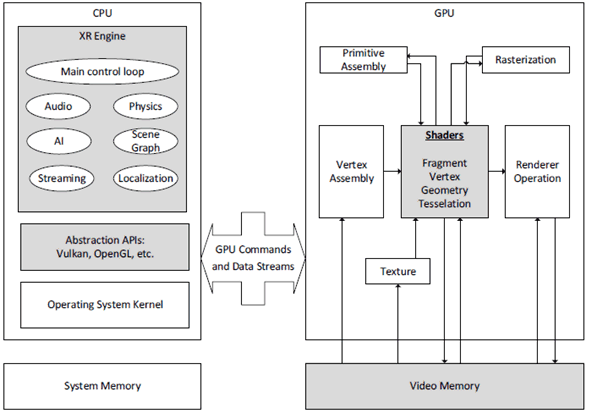
An XR engine is a software-development environment designed for people to build XR experiences such as games and other XR applications. The core functionality typically provided by XR engines include a rendering engine ("renderer") for 2D or 3D graphics, a physics engine or collision detection (and collision response), sound, scripting, animation, artificial intelligence, networking, streaming, memory management, threading, localization support, scene graph, and may include video support.
Typical components are summarized below
- Rendering engine: This engine basically provides the functionalities as documented in clause 4.2.2 with a set of well defined APIs. In summary, the rendering engine generates animated 3D graphics by any of a number of methods (rasterization, ray-tracing etc.). Instead of being programmed and compiled to be executed on the CPU or GPU directly, most often rendering engines are built upon one or multiple rendering application programming interfaces (APIs), such as Direct3D, OpenGL, or Vulkan which provide a software abstraction of the graphics processing unit (GPU).
- Audio engine: The audio engine is the component which consists of algorithms related to the loading, modifying and output of sound through the client's speaker system. At a minimum it is able to load, decompress and play sound files. More advanced audio engines can calculate and produce such configurations as Doppler effects, echoes, pitch/amplitude adjustments, oscillation, etc. The audio engine can perform calculations on the CPU, or on a dedicated ASIC. Abstraction APIs, such as OpenAL, SDL audio, XAudio 2, Web Audio, etc. are available.
- Physics engine: The physics engine is responsible for emulating the laws of physics realistically within the XR application. Specifically, it provides a set of functions for simulating physical forces and collisions, acting on the various objects within the scene at run time.
- Artificial intelligence (AI): AI is usually outsourced from the main XR engine into a special module. XR applications may implement very different AI systems, and thus, AI is considered to be specific to the particular XR application for which it is created.

As mentioned above, key aspects of such XR engines and abstraction layers is the integration of advanced functionalities for new XR experiences including video, sound, scripting, networking, streaming, localization support, and scene graphs. By well-defined APIs, XR engines may also be distributed, where part of the functionality is hosted in the network on an XR Server and other parts of the functionality are carried out in the XR device.
GPU operations and rendering is dealt with in clause 4.4.2.
In the remainder of this Technical Report, the term XR engine is used to provide any type of typical XR functionalities as mentioned above. A key issue is the functional integration of potentially 3GPP defined technologies, including well defined APIs and interfaces for the usability and benefit of XR application developers.
4.4.2 Briefly on Rendering Pipelines p. 30
Rendering or graphics pipelines are basically built by a sequence of shaders that operate on different buffers in order to create a desired output. Shaders are a type of computer programs that were originally used for shading (the production of appropriate levels of light, darkness, and colour within an image), but which now perform a variety of programmable functions in various fields of computer graphics as well as image and video processing.
The input to the shaders is handled by the application, which decides what kind of data each stage of the rendering pipeline should operate on. Typically this data is 3D assets consisting of geometric primitives and material components. The application controls the rendering by providing the shaders with instructions describing how models should be transformed and projected on a 2D surface.
Generally there are 2 types of rendering pipelines (i) rasterization rendering and (ii) ray-traced rendering (a.k.a. ray-tracing) as shown in Figure 4.4.2-1.
- Rasterization is the task of taking an image described in a vector graphics format (shapes) and converting it into a raster image (a series of pixels, which, when displayed together, create the image which was represented via shapes). The rasterized image may then be displayed on a computer display, video display or printer, stored in a bitmap file format, or processed and encoded by regular 2D image and video codecs.
- Ray tracing heavy pipelines are typically considered as more computationally expensive thus less suitable for real-time rendering. However, in recent years real-time ray tracing has leaped forward due to improved hardware support and advances in ray tracing algorithms and post-processing.

Figure 4.4.2-1: Rasterized (left) and ray-tracing based (right) rendering
(⇒ copy of original 3GPP image)
(⇒ copy of original 3GPP image)
4.4.3 Real-time 3D Rendering p. 31
3D rendering is the process of converting 3D models into 2D images to be presented on a display. 3D rendering may include photorealistic or non-photorealistic styles. Rendering is the final process of creating the actual 2D image or animation from the prepared scene, i.e. creating the viewport. Rendering ranges from the distinctly non-realistic wireframe rendering through polygon-based rendering, to more advanced techniques such as ray tracing. The 2D rendered viewport image is simply a two dimensional array of pixels with specific colours.
Typically, rendering needs to happen in real-time for video and interactive data. Rendering for interactive media, such as games and simulations, is calculated and displayed in real-time, at rates of approximately 20 to 120 frames per second. The primary goal is to achieve a desired level of quality at a desired minimum rendering speed. The impact of the frame rate for the rendering pipeline is discussed in details in clause 4.2.2. The rapid increase in computer processing power and in the number of new algorithms has allowed a progressively higher degree of realism even for real-time rendering. Real-time rendering is often based on rasterization and aided by the computer's GPU.
Animations for non-interactive media, such as feature films and video, can take much more time to render. Non real-time rendering enables use of brute-force ray tracing to obtain a higher image quality.
However, in the context of XR in this Technical Report, the assumption of rendering is to be real-time to react to updated XR pose information, updates in the scene as produced, and so on.
4.4.4 Network Rendering and Buffer Data p. 31
In several applications, rendering or pre-rendering is not exclusively carried out in the device GPU, but assisted or split across the network. If this is the case, then the following aspects matter:
- The type of buffers that are pre-rendered/baked in the network. Typical buffer formats are summarized below.
- The format of the buffer data. Again, some data is collected below.
- The number of parallel buffers that are handled
- Specific delay requirements of each of the buffers
- The dimensions of the buffers in terms of size and time
- The ability to compress the buffers using conventional video codecs.
- Vertex Buffer: A rendering resource managed by a rendering API holding vertex data. May be connected by primitive indices to assemble rendering primitives such as triangle strips.
- Depth Buffer: A bitmap image holding depth values (either a Z buffer or a W buffer), used for visible surface determination, during rasterization of 3D scenes.
- Texture Buffer: A region of memory (or resource) used as both a render target and a texture map. A texture map is defined as an image/rendering resource used in texture mapping, applied to 3D models and indexed by UV mapping for 3D rendering. Texture/Image represents a set of pixels. Texture buffers have assigned parameters to specify creation of an Image. It can be 1D, 2D or 3D, can have various pixel formats (like R8G8B8A8_UNORM or R32_SFLOAT) and can also consist of many discrete images, because it can have multiple array layers or MIP levels (or both). As an example, detailed formats for Vulkan are provided here:
- Frame Buffer: a region of memory containing a bitmap that drives a video display. These frame buffers are in raster formats, i.e. they are the result of rasterization. It is a memory buffer containing a complete frame of data. Frame buffers are supported by swap chains being a series of virtual frame buffers utilized by the graphics card and graphics API for frame rate stabilization and several other functions. In every swap chain there are at least two buffers. The first frame buffer, the screen buffer, is the buffer that is rendered to the output of the video card. The remaining buffers are known as backbuffers. Each time a new frame is displayed, the first backbuffer in the swap chain takes the place of the screenbuffer, this is called presentation or swapping. A variety of other actions may be taken on the previous screenbuffer and other backbuffers (if they exist). The screen buffer may be simply overwritten or returned to the back of the swap chain for further processing. The action taken is decided by the client application and is API dependent.
- Uniform Buffer: A Buffer Object that is used to store uniform data for a shader program. It can be used to share uniforms between different programs, as well as quickly change between sets of uniforms for the same program object. A uniform is a global Shader variable declared with the "uniform" storage qualifier. These act as parameters that the user of a shader program can pass to that program. Uniforms are so named because they do not change from one shader invocation to the next within a particular rendering call.