Content for TS 23.548 Word version: 18.6.0
1…
4…
4.3
5…
6…
6.2.2.3…
6.2.3…
6.2.3.2.3…
6.2.3.2.5…
6.2.3.3…
6.3…
6.4…
6.5…
6.6
6.7…
6.7.2.4…
6.7.2.6…
6.7.3…
6.8…
7…
A
B…
F…
6.3 Edge Relocation
6.3.1 General
6.3.2 Edge Relocation Involving AF Change
6.3.3 Edge Relocation Using EAS IP Replacement
6.3.3.1 EAS IP Replacement Procedures
6.3.3.1.1 Enabling EAS IP Replacement Procedure by AF
6.3.3.1.2 EAS IP Replacement Update upon DNAI and EAS IP Change
6.3.3.1.3 Disabling EAS IP Replacement Procedure
6.3.3.2 Enhancement to AF Influence
6.3.4 AF Request for Simultaneous Connectivity over Source and Target PSA at Edge Relocation
6.3.5 Packet Buffering for Low Packet Loss
6.3.6 Edge Relocation Considering User Plane Latency Requirement
6.3.7 Edge Relocation Triggered by AF
...
...
6.3 Edge Relocation p. 37
6.3.1 General p. 37
Edge Relocation refers to the procedures supporting EAS changes and/or PSA UPF relocation.
Edge Relocation may be triggered by an AF request (e.g. due to the load balance between EAS instances in the EHE) or by the network (e.g. due to the UE mobility).
With Edge Relocation, the user plane path may be re-configured to keep it optimized. This may be done by PDU Session re-establishment using SSC mode 2/3 mechanisms or Local PSA UPF relocation using UL CL and BP mechanisms. The corresponding procedures are defined in TS 23.501 and TS 23.502.
Due to Edge Relocation, the UE may need to re-discover a new EAS and establish the connectivity to the new EAS to continue the service. The re-discovery of EAS is specified in clause 6.2.
Edge Relocation may result in AF relocation, for example, as part of initial PDU Session Establishment, a central AF may be involved. However, due to Edge Relocation another AF serving the Edge Applications is selected.
The trigger of Edge Relocation by the network is specified in clause 4.3.6.3 of TS 23.502. Some EAS (re-)Discovery procedures in clause 6.2 may also trigger Edge Relocation.
This clause further describes the following procedures:
- Edge Relocation involving AF change.
- Edge Relocation using EAS IP replacement.
- AF request for simultaneous connectivity for source and target PSA.
- Packet buffering for low Packet Loss.
- Edge Relocation considering User Plane Latency Requirements.
- Edge Relocation triggered by AF
- Edge Relocation for a set of UEs for common DNAI.
6.3.2 Edge Relocation Involving AF Change p. 38
This clause is related to scenarios where distributed Edge Application Server (EAS) deployed in local part of a Data Network or a central AS are relocated, and where the (E)AS relocation also implies AF relocation i.e. AF instance change.
Application Function influence on traffic routing mechanism as described in clause 5.6.7 of TS 23.501 can be applied for a relocation of the AF. In the case that AF sends AF request via NEF, the target AF may invoke Nnef_TrafficInfluence_Create to deliver the relocation related information, including notification target address based on the procedure described in clause 4.3.6.2 of TS 23.502. Also, the source AF or target AF may invoke Nnef_TrafficInfluence_Update service operation to deliver the relocation information, including AF ID and notification target address based on the procedure described in clause 4.3.6.2 of TS 23.502.
Also if the AF relocation occurs during the early/late notification procedure described in clause 4.3.6.3 of TS 23.502, the target AF invokes Nnef_TrafficIfluence_Create /Update at step 4e-a or Npcf_PolicyAuthorization_Create at step 4g-a to deliver the notification target address of the AF. In the case that AF directly interacts with PCF, the target AF may invoke Npcf_PolicyAuthorization _Create, or the source AF/target AF may invoke Npcf_PolicyAuthorization _Update service operation to deliver relocation information including notification target address based on the procedure described in clause 4.3.6.4 of TS 23.502.
In the case of Edge relocation between two DNAI(s), an AF relocation may be triggered by SMF, e.g. due to UE mobility. In such cases, the SMF provides as described in clause 4.3.6.3 of TS 23.502 during early/late notification procedure the source AF with target AF ID as defined in Table 6.2.3.4-1. Target AF ID is used by source AF to communicate with the target AF.
6.3.3 Edge Relocation Using EAS IP Replacement p. 38
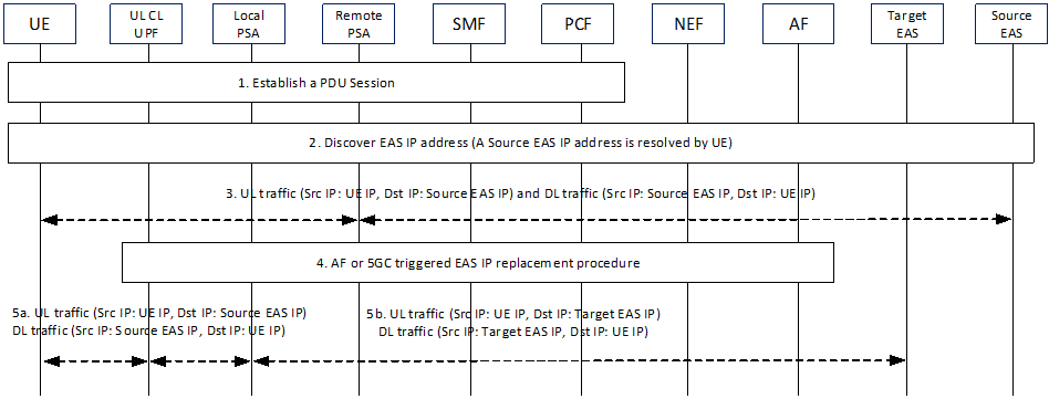
EAS IP replacement enables the Local PSA UPF to replace the source/old Target EAS IP address and port number with the target/new target EAS IP address and port number for the Destination IP address and Destination Port number field of the uplink traffic and replace the target/new target EAS IP address and port number with the source/old Target EAS IP address and port number for the Source IP address and Source Port number field of the downlink traffic based on the enhanced AF Influence information for EAS IP replacement (i.e. source EAS IP address and port number, target EAS IP address and port number). The source AS IP address and port number are the destination IP address and port number of the uplink traffic, generated by UE, for a service subject to Edge Computing. The source EAS IP address is the one discovered by UE for a service subject to Edge Computing.
To support Edge Relocation using EAS IP address and Port number replacement, in this clause the SMF shall instruct the UPF to use the FAR that contains Information elements of "IP Address and Port Number Replacement".
EAS IP replacement requires support of TCP/TLS/QUIC context transfer between EASs.
6.3.3.1 EAS IP Replacement Procedures p. 39
6.3.3.1.1 Enabling EAS IP Replacement Procedure by AF p. 39

Step 1.
UE requests to establish a PDU Session.
Step 2.
UE is preconfigured with the Source EAS IP address or discovers the IP address of the application server for the service subject to Edge Computing and the Source EAS IP address is returned to the UE via EAS Discovery procedure as described in clause 6.2.
Step 3.
UE communicates with the Source EAS.
Step 4a.
EAS Relocation may be triggered by AF (e.g. due to the load balance between EAS instances in the EHE). When AF detects that the EAS is capable of runtime context mirroring and an optimal EAS is found, then AF decides to influence the traffic routing in 5GC. For the common DNAI case, the AF may determine that there is an optimal common DNAI (i.e. target common DNAI). The AF may select Target EAS corresponding to the target common DNAI for each UE belonging to the set of UEs. The EAS IP replacement information (i.e. source EAS IP address and port number, target EAS IP address and port number) is sent to the SMF within the AF Influence information and the SMF reconfigures the UL CL UPF for local traffic routing and Local PSA with EAS IP replacement information.
UL CL is configured by SMF to forward UL packet to Local PSA if the destination IP address is the Source EAS IP address.
Local PSA is configured by SMF to enforce the FAR as described in step 5.
Detailed enhancement to the AF Influence procedure is described in clause 6.3.3.2.
If a new Local PSA is selected by SMF, the SMF may configure the new Local PSA to buffer the uplink traffic per clause 6.3.5 and enforce the "Outer Header Creation" and "Outer Header Removal" as described in step 5.
If AF is not notified by 5GC that the 5GC supports EAS IP replacement mechanism, the AF does not include the target EAS identifier and does not initiate the AF triggered EAS IP replacement procedure.
If the 5GC does not support EAS IP replacement capability, the SMF should reject the AF request and step 5 is skipped.
Step 4b.
EAS Relocation may be also triggered by 5GC (e.g. due to UE Mobility). For the common DNAI case, a SMF may determine that there is an optimal common DNAI (i.e. target common DNAI). If target common DNAI is not available, the SMF determines Target Common DNAI.. The SMF selects the common DNAI according to clause 6.2.3.2.4. When Early/Late Notification procedure with enhancement described in clause 6.3.3.2 is triggered, the SMF notifies AF about the target DNAI or target common DNAI and may provide the capability of supporting EAS IP replacement in 5GC. Based on the target DNAI or target common DNAI, the AF selects a proper target EAS, then the AF triggers to mirror the runtime context between Source EAS and Target EAS. Once the Target EAS is ready, AF responds to SMF about the EAS IP replacement information. During the addition or change of UL CL and Local PSA as described in clause 4.3.5.4, 4.3.5.6 or 4.3.5.7 of TS 23.502, SMF may (re)configure Local PSA for EAS IP address replacement between Source EAS and Target EAS.
Step 5.
Local PSA starts to perform FARs as instructed by SMF, which results in EAS IP address replacement:
- For UL traffic, the destination IP address and port number are replaced with the Target EAS IP address and port number;
- For DL traffic, the source IP address and port number are replaced back with the Source EAS IP address and port number.
6.3.3.1.2 EAS IP Replacement Update upon DNAI and EAS IP Change p. 40

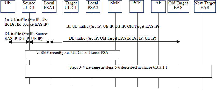
Step 1.
Steps 3-4 are same as steps 5-6 described in clause 6.3.3.1.1 except that the UL CL, Local PSA and Target EAS in clause 6.3.3.1.1 are replaced by Target UL CL, Local PSA2 and new Target EAS respectively.
For UL traffic, the destination IP address is replaced with the old Target EAS IP address at Local PSA; for DL traffic, the source IP address is replaced back with the Source EAS IP address at Local PSA.
Step 2.
SMF configures Target UL CL with forwarding rules and Local PSA2 with FARs, as described in step 4 of clause 6.3.3.1.1.
6.3.3.1.3 Disabling EAS IP Replacement Procedure p. 41

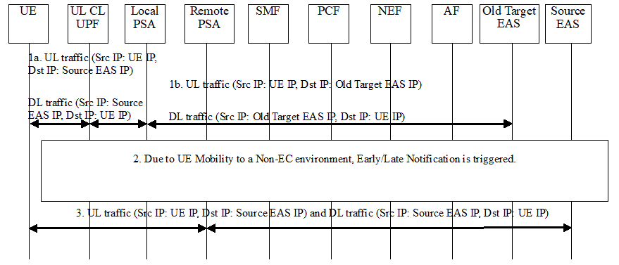
Step 1.
Local PSA performs FARs as instructed by SMF, which results in EAS IP address replacement:
Step 2.
- For UL traffic, the destination IP address and port number are replaced with the old Target EAS IP address and port number;
- For DL traffic, the source IP address and port number are replaced back with the Source EAS IP address and port number.
Due to UE Mobility to a Non-EC environment, when Early/Late Notification is triggered for the change from the UP path status where a DNAI applies to a status where no DNAI applies, AF knows the UE moves out of EC environment and mirrors the runtime session context from old Target EAS to Source EAS. Once ready, the AF indicates SMF without providing source/target EAS IP addresses and port numbers, so the SMF disables the local routing at UL CL and the EAS IP replacement at Local PSA for this PDU Session.
Step 3.
UL and DL traffic goes through Remote PSA, no EAS IP address replacement happens at Remote PSA.
6.3.3.2 Enhancement to AF Influence p. 41
The AF may additionally include Source and Target EAS IP address(es) and Port number(s) in the Nnef_TrafficInfluence_Create /Update or Nnef_TrafficInfluence_AppRelocationInfo or Nsmf_EventExposure_AppRelocationInfo request. Based on the Source EAS IP address(es) and Port number(s), the SMF knows which service flow(s) is(are) subject to EAS IP Replacement.
Using Early/Late Notification procedure, the SMF may notify the AF about the capability of supporting EAS IP replacement in 5GC, the AF sends an/a early/late notification response to the SMF when EAS relocation is completed. The SMF sends the FARs to (target) Local PSA UPF and (target) Local PSA UPF starts the EAS IP address replacement as described in clause 6.3.3.1.
For load balancing purpose, the AF may move some UE(s) from the old Target EAS to the New Target EAS in the same L-DN identified by the DNAI. For the abnormal condition of EAS, the AF may move all the UEs being served by the source EAS to a target EAS in the same L-DN. For those purposes, the AF needs to include List of UEs, the source/old Target EAS IP address and port number for the impacted DNAI, the (new) Target EAS IP address and port number for the impacted DNAI in the Nnef_TrafficInfluence_Create /Update request. If 5GC does not support EAS IP replacement capability, the SMF should reject this AF request.
The additional parameters for enabling the EAS IP Replacement are defined in clause 5.6.7.1 of TS 23.501 and clauses 4.3.6.3 and 4.3.6.4 of TS 23.502.
6.3.4 AF Request for Simultaneous Connectivity over Source and Target PSA at Edge Relocation p. 42
EAS relocation can make use of network capabilities that, at PSA change, provide simultaneous connectivity over the source and the target PSA during a transient period. This is described in Annex F.
AF may issue a request to the network on whether to provide simultaneous connectivity over the source and the target PSA at edge relocation. This may trigger the SMF to use a re-anchoring procedure that provides simultaneous connectivity over the source and target PSA, as described in TS 23.502:
- For Session Breakout, in clause 4.3.5.7 for Simultaneous change of Branching Point or UL CL and additional PSA for a PDU Session. This could involve the establishment of a temporary N9 forwarding tunnel between the source UL CL and target UL CL.
- "Keep existing PSA" indication: If this indication is included, the SMF may decide to use a re-anchoring procedure that provides simultaneous connectivity over the source and target PSA, as described above.
- "Keep existing PSA timer": its value indicates the minimum time interval to be considered for inactivity for the traffic described. It may overwrite the SMF configurable period of time for how long the existing PSA is to be maintained after all active traffic ceases to flow on it.
6.3.5 Packet Buffering for Low Packet Loss p. 42
This procedure aims at synchronizing between EAS relocation and UL traffic from the UE, ensuring that UL traffic from the UE is sent to the new EAS only when EAS context transfer has been carried out.
This procedure may be applied at change of local PSA. It consists of buffering uplink packets in the target PSA in order to prevent there is packet loss if the application client sends UL packets to a new EAS before the new EAS is prepared to handle them. During the buffering, the old EAS may continue to serve the UE over the former PSA.
Buffering starts upon request by AF and continues till AF indicates otherwise. The EAS relocation procedure (e.g. the migration of the service context) happens at the application layer. That is outside the scope of 3GPP.
As an alternative to this procedure, upper layer solutions can provide the needed synchronization between EAS relocation and UL traffic from the UE.
Buffering of uplink packets is not meant to apply to all traffic being offloaded at the new PSA. AF may request the buffering for the UL traffic of applications that require so. When the AF subscribes Early/Late Notification of UP path change for a specific application, Traffic Description for this application is provided as described in clause 5.6.7 of TS 23.501. When AF receives such an Early/Late Notification and indicates that uplink traffic buffering is needed in the response (step 2 in Figure 6.3.5-1), this uplink traffic buffering is then activated for the traffic described by Traffic Description provided in the subscription to Early/Late Notification.

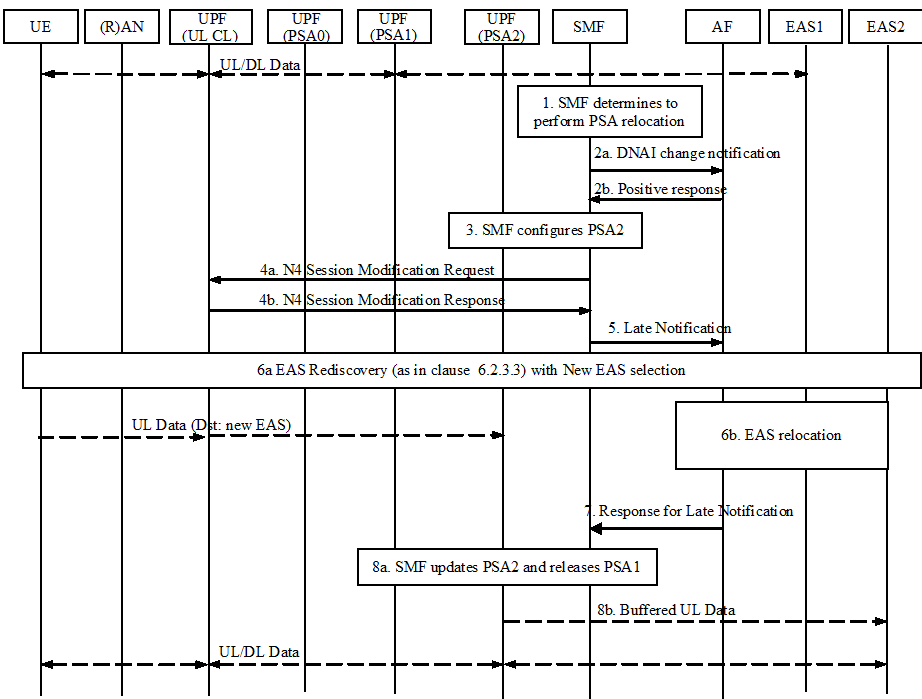
Step 1.
The SMF decides to change the local PSA of a PDU Session with UL CL or SSC mode 3.
Step 2.
The SMF may send an early notification to the AF after target PSA (i.e. PSA2) is selected and waits for a notification response from the AF. The AF may reply in positive to the notification by indicating that buffering of uplink traffic to the target DNAI is needed as long as traffic to the target DNAI is not authorized by the AF. This is e.g. as defined in steps 1 and 2 of TS 23.502 Figure 4.3.6.3-1.
Step 3.
For the procedures with ULCL/BP, the SMF configures the PSA2 as specified in step 2 in clause 4.3.5.6 and step 2 in clause 4.3.5.7 of TS 23.502, which may request the PSA2 to buffer uplink traffic. The PSA1 (i.e. source PSA) keeps receiving downlink traffic from EAS1 and send it to the UE until it is released in step 7.
For the procedures with SSC mode 3, the SMF configures the PSA2 as specified in step 4 in clause 4.3.5.2 and in step 5-6 in clause 4.3.5.4 of TS 23.502, which may request the PSA2 to buffer uplink traffic.
Step 4.
For the procedures with ULCL/BP, the SMF sends an N4 Session Modification Request to the UL CL to update the UL CL rules regarding to the traffic flows that the SMF tries to steer to PSA2. This is e.g. as defined in TS 23.502 Figure 4.3.5.7-1 step 3.
Step 5.
The SMF sends a Late Notification to the AF. This corresponds e.g. to step 4a-c of TS 23.502 Figure 4.3.6.3-1 and is e.g. also described in step 9 of TS 23.502 Figure 4.3.5.7-1.
Step 6a.
A new EAS is selected by the application (e.g. at DNS cache entry expiry, the DNS Query is resolved and the response includes a new EAS that is near the new PSA (PSA2)). Any traffic sent to the new EAS is buffered at PSA2.
Step 6b.
The application layer completes the EAS relocation (This corresponds to step 4d of TS 23.502 Figure 4.3.6.3-1). The UE context is completely relocated from the old EAS to new EAS. The old EAS stops to serve the UE
Step 7.
When EAS relocation is completed, the AF sends a notification response to the SMF. This corresponds to step 4e-g of TS 23.502 Figure 4.3.6.3-1 (and is e.g. also described in step 6 or 7 of TS 23.502 Figure 4.3.5.7-1) and may indicate that buffering of uplink traffic to the target DNAI is no more needed as traffic to the target DNAI /EAS is now authorized by the AF.
If the AF is changed during EAS relocation, see the details indicated in clause 6.3.2.
Step 8.
(if AF has indicated that buffering of uplink traffic to the target DNAI is no more needed as traffic to the target DNAI /EAS is now authorized by the AF) The SMF updates the PSA2 by indicating the PSA2 to send the buffered uplink packets (step 8b) and to stop buffering.
The SMF releases PSA1.
6.3.6 Edge Relocation Considering User Plane Latency Requirement p. 44
Edge relocation may be performed considering user plane latency requirements provided by the AF.
In a network deployment where the estimated user plane latency between the UE and the potential PSA-UPF is known to the SMF, the 5GC provides the enhancement of AF influence to consider the user plane latency requirements requested by the AF so that the SMF decides to relocate the PSA-UPF based on AF requested requirements.
The AF may provide user plane latency requirements to the network via AF traffic influence request as described in clause 5.2.6.7 of TS 23.502. The user plane latency requirements may include the following information:
- Maximum allowed user plane latency: The value of this information is the target user plane latency. The SMF may use this value to decide whether edge relocation is needed to ensure that the user plane latency does not exceed the value. The SMF may decide whether to relocate the PSA UPF to satisfy the user plane latency.
- In the case that the maximum allowed user plane latency is requested, the SMF decides not to perform PSA UPF relocation if the serving PSA satisfies the maximum allowed user plane latency. Otherwise, the SMF may decide to perform PSA UPF relocation if the target PSA UPF satisfies the maximum user plane latency. The SMF may select the PSA UPF with the shortest user plane latency among the PSA UPFs satisfying the maximum user plane latency requirements.
6.3.7 Edge Relocation Triggered by AF p. 44
The AF may invoke the AF request targeting an individual UE address procedure as described in clause 4.3.6.4 of TS 23.502, due to EAS relocation. The EAS relocation may be due to AF internal triggers e.g. EAS load balance or maintenance, etc. or due to UP path change notification from SMF. The EAS relocation may include AF change or AF not change. The EAS relocation can happen with or without DNAI change. The AF may include the following information: Indication for EAS Relocation, target DNAI, traffic descriptor information and N6 routing information at target DNAI in the Nnef_TrafficInfluence_Create /Update Request to the NEF, or Npcf_PolicyAuthorization_Create /Update Request to the PCF. When the PCF receives an AF request for the same application, then the latest AF request message take precedence over any previous request if the traffic descriptor information is same.
The AF may invoke the AF request targeting a set of UEs as described in clause 4.3.6.2 of TS 23.502, due to change of common EAS/common DNAI used by the set of UEs. Similar as the Edge relocation triggered by AF with target DNAI, the common DNAI is included instead of the target DNAI.