Content for TS 23.548 Word version: 18.4.0
4.3 Connectivity Models p. 10
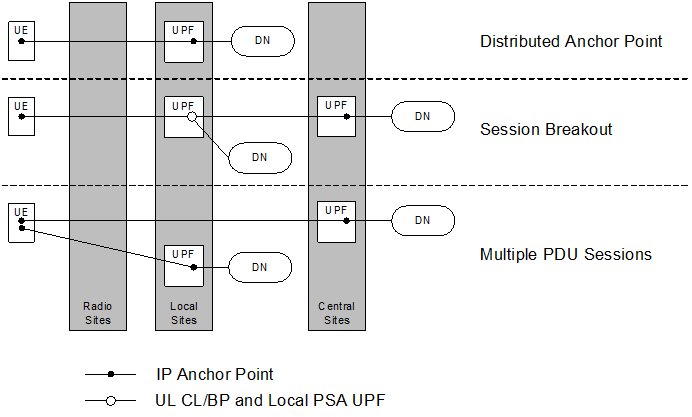
5GC supports the following connectivity models to enable Edge Computing:
- Distributed Anchor Point: For a PDU Session, the PSA UPF is in a local site, i.e. close to the UE location. The PSA UPF may be changed e.g. due to UE mobility and using SSC mode 2 or 3.
- Session Breakout: A PDU Session has a PSA UPF in a central site (C-PSA UPF) and one or more PSA UPF in the local site (L-PSA UPF). The C-PSA UPF provides the IP Anchor Point when UL Classifier is used. The Edge Computing application traffic is selectively diverted to the L-PSA UPF using UL Classifier or multi-homing Branching Point mechanisms. The L-PSA UPF may be changed due to e.g. UE mobility.
- Multiple PDU Sessions: Edge Computing applications use PDU Session(s) with a PSA UPF(s) in local site(s). The rest of applications use PDU Session(s) with PSA UPF(s) in the central site(s). Any PSA UPF may be changed due to e.g. UE mobility and using SSC mode 3 with multiple PDU Sessions.
